MIXBUS VBM
2 December 2021
2.2.6 Pan/Balance Control
As mentioned at the beginning of Section
mono input channels have a Pan control and
stereo input channels have a Balance control. The pan/balance control setting from the channel
strip is common across all Program and MixMinus bus destinations. However the pan/balance at
any particular bus can be unlinked in the Bus Sends section of Program or MixMinus buses. See
Section
On stereo input channels the balance control adjusts the relative levels of the left and right
channel strip outputs to the buses. At centre the signal levels to the left and right sides of the
buses is 50% of the channel level. Sliding the panner full left will send 100% of the channel left
side to bus left and 0% of channel right side to bus right, and vice versa.
On mono input channels, the mono signal is sent to bus left and bus right according to the
position of the slider.
2.2.7 Channel Slate
The channel slate is a name plate the same as the name plate at the top of the channel.
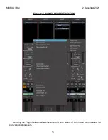
Right-clicking on the slate brings up the same options shown in
2.2.8 Mute and Solo Buttons
Engaging the Mute button mutes all outputs from the channel strip.
Engaging the Solo button solos the channel on the monitor output. Active channel sends and
outputs are not affected. The solo mode (for example, PFL or AFL) is globally selected on the
Monitor strip (see Section
2.2.9 Level Displays
The two side-by-side readouts show numerically the fader setting (left one) and the output
meter reading (right one). If the output level ever exceeds 0 dBFS and clips, the output level
readout will turn red. After you have corrected the level issue, clicking on the readout will clear the
clip indication.
2.2.10
Fader
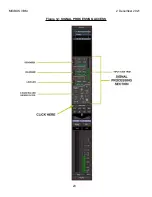
The fader controls the channel strip output level to the Program buses. It also has a horizontal
bar indicating nominal level (0dB gain).
27
Summary of Contents for Mixbus VBM
Page 1: ...MANUAL VERSION 1 5 DATE 2 December 2021 NOTES For VBM 1 2 release ...
Page 8: ...MIXBUS VBM 2 December 2021 Figure 2 VBM INPUT SECTION 8 ...
Page 10: ...MIXBUS VBM 2 December 2021 Figure 3 VBM STEREO CHANNEL STRIP 10 ...
Page 11: ...MIXBUS VBM 2 December 2021 Figure 4 VBM MONO CHANNEL STRIP 11 ...
Page 18: ...MIXBUS VBM 2 December 2021 Figure 11 CHANNEL EXTERNAL SEND 18 ...
Page 20: ...MIXBUS VBM 2 December 2021 Figure 12 SIGNAL PROCESSING ACCESS 20 ...
Page 23: ...MIXBUS VBM 2 December 2021 Figure 14 PROGRAM BUS ASSIGN BUTTONS 23 ...
Page 33: ...MIXBUS VBM 2 December 2021 Figure 24 VCA MASTER 33 ...
Page 36: ...MIXBUS VBM 2 December 2021 Figure 27 VBM BUS MASTERS 36 ...
Page 38: ...MIXBUS VBM 2 December 2021 Figure 28 PROGRAM BUS MASTER 38 ...
Page 42: ...MIXBUS VBM 2 December 2021 Figure 31 PROGRAM BUS MASTER SHOWING SENDS SECTION 42 ...
Page 47: ...MIXBUS VBM 2 December 2021 Figure 36 MIX MINUS BUS MASTER 47 ...
Page 51: ...MIXBUS VBM 2 December 2021 Figure 38 VBM MONITOR STRIP 51 ...
Page 53: ...MIXBUS VBM 2 December 2021 Figure 39 MONITOR SELECTOR 53 ...
Page 54: ...MIXBUS VBM 2 December 2021 Figure 40 MONITOR STRIP IN SOLO 54 ...
Page 56: ...MIXBUS VBM 2 December 2021 Figure 42 ROUTING TOOL 56 ...
Page 57: ...MIXBUS VBM 2 December 2021 Figure 43 SHOWING A PROGRAM BUS TO PROGRAM BUS CONNECTION 57 ...
Page 58: ...MIXBUS VBM 2 December 2021 Figure 44 MONITOR STRIP CONNECTION TO EXTERNAL INTERFACE 58 ...
Page 64: ...MIXBUS VBM 2 December 2021 Figure 48 ACE IFB SIDECHAIN INPUT CONNECTION 64 ...
Page 67: ...MIXBUS VBM 2 December 2021 Figure 50 ABOUT WINDOW END OF VBM USER MANUAL 67 ...

