MIXBUS VBM
2 December 2021
2.4.1.2 Redirect Section
The Redirect section provides for inserting processing plugins and additional sends out of the
bus strip. The functioning of this section is identical to that in the Input channel strip, as covered
in Section
2.4.1.3 Program Bus Signal Processing
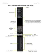
Clicking on the "VBM Strip" button on any input channel or bus master displays the signal
processing sections on all input channel strips and buses.
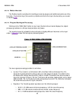
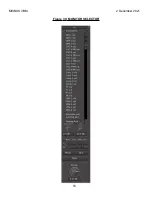
The signal processing available on the on buses is slightly different than that on the Input
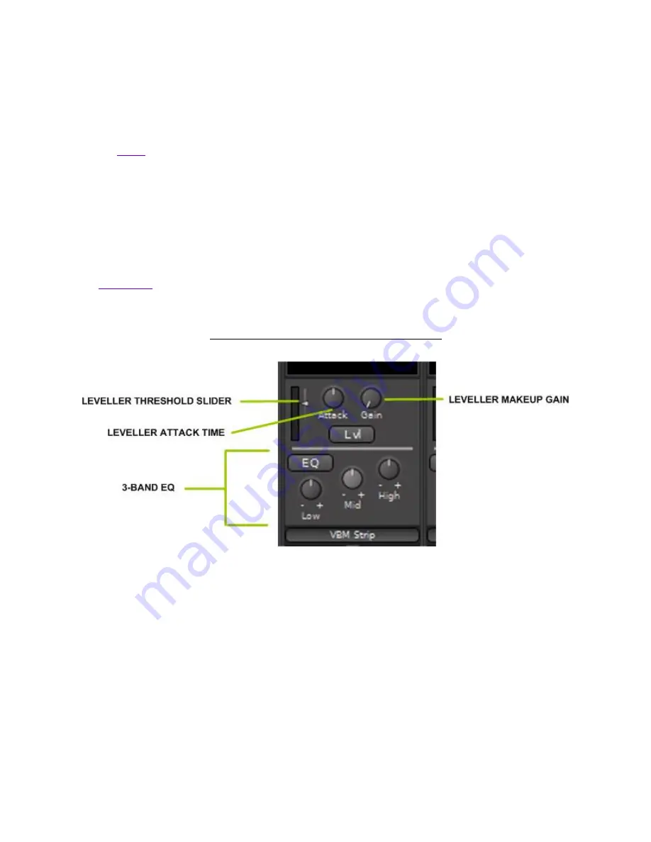
shows the bus signal processing detail.
Figure
30
: BUS SIGNAL PROCESSING
The bus signal processing provided is as follows.
Leveler: The Leveler is a compressor with a low fixed ratio and release time. It is
designed to gently smooth out the peaks in a wide range of signals. The slider on the
left adjusts the limiting threshold from 0 dB to -40 dB. The Attack knob sets the attack
time over a range of 4ms to 100 ms. The Gain knob provides makeup gain over a range
0dB to 20 dB. The "Lvl" button turns the processing on and off. The meter bar indicates
the instantaneous amount of gain reduction.
Equalizer: The 3 band equalizer operates over the following ranges:
o
LOW: +/-15 dB boost/cut shelving response, 125 Hz corner frequency
o
MID: +/-15 dB boost/cut bell response, 900 Hz centre frequency
o
HI: +/-15 dB boost/cut shelving response, 3200 Hz corner frequency
40
Summary of Contents for Mixbus VBM
Page 1: ...MANUAL VERSION 1 5 DATE 2 December 2021 NOTES For VBM 1 2 release ...
Page 8: ...MIXBUS VBM 2 December 2021 Figure 2 VBM INPUT SECTION 8 ...
Page 10: ...MIXBUS VBM 2 December 2021 Figure 3 VBM STEREO CHANNEL STRIP 10 ...
Page 11: ...MIXBUS VBM 2 December 2021 Figure 4 VBM MONO CHANNEL STRIP 11 ...
Page 18: ...MIXBUS VBM 2 December 2021 Figure 11 CHANNEL EXTERNAL SEND 18 ...
Page 20: ...MIXBUS VBM 2 December 2021 Figure 12 SIGNAL PROCESSING ACCESS 20 ...
Page 23: ...MIXBUS VBM 2 December 2021 Figure 14 PROGRAM BUS ASSIGN BUTTONS 23 ...
Page 33: ...MIXBUS VBM 2 December 2021 Figure 24 VCA MASTER 33 ...
Page 36: ...MIXBUS VBM 2 December 2021 Figure 27 VBM BUS MASTERS 36 ...
Page 38: ...MIXBUS VBM 2 December 2021 Figure 28 PROGRAM BUS MASTER 38 ...
Page 42: ...MIXBUS VBM 2 December 2021 Figure 31 PROGRAM BUS MASTER SHOWING SENDS SECTION 42 ...
Page 47: ...MIXBUS VBM 2 December 2021 Figure 36 MIX MINUS BUS MASTER 47 ...
Page 51: ...MIXBUS VBM 2 December 2021 Figure 38 VBM MONITOR STRIP 51 ...
Page 53: ...MIXBUS VBM 2 December 2021 Figure 39 MONITOR SELECTOR 53 ...
Page 54: ...MIXBUS VBM 2 December 2021 Figure 40 MONITOR STRIP IN SOLO 54 ...
Page 56: ...MIXBUS VBM 2 December 2021 Figure 42 ROUTING TOOL 56 ...
Page 57: ...MIXBUS VBM 2 December 2021 Figure 43 SHOWING A PROGRAM BUS TO PROGRAM BUS CONNECTION 57 ...
Page 58: ...MIXBUS VBM 2 December 2021 Figure 44 MONITOR STRIP CONNECTION TO EXTERNAL INTERFACE 58 ...
Page 64: ...MIXBUS VBM 2 December 2021 Figure 48 ACE IFB SIDECHAIN INPUT CONNECTION 64 ...
Page 67: ...MIXBUS VBM 2 December 2021 Figure 50 ABOUT WINDOW END OF VBM USER MANUAL 67 ...


