MIXBUS VBM
2 December 2021
6.0
Appendix 1: ACE IFB Plugin
6.1 Description
The ACE IFB plugin is automatically inserted on all MixMinus buses when they are created.
This plugin is the mechanism to provide talkback audio to the contributor. The plugin itself is a
4in x 2out mixer/ducker. Stereo mix minus audio comes in through 2 inputs. Talkback/comms
sources are fed to the other 2 inputs. The plugin will then duck the mix minus audio based on the
threshold setting when the talkback happens.
6.2 Use
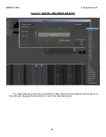
As on any plugin in VBM, double-clicking will bring up its control panel as shown in
The control parameters for the ducker are self evident. Shown is the control panel for the plugin
on MixMinus bus GVC A.
The ducking function requires connections to the sidechain inputs in order to operate. These
can be attached through the Pin Connections window, accessed either by right clicking on the
plugin in the bus redirect section, or by clicking on the pin connection button in the plugin control
panel, as shown in
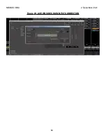
The pin connection window is shown in
. Note the 4 inputs at the top of the plugin, of
which 2 are the through audio paths and are automatically connected, and 2 are sidechain inputs.
Thus, the ducker function can be controlled from 2 different sources.
To add a sidechain input to operate the ducker, click on the "Sidechain" button and
selector/deselector buttons will appear. A wide selection of signals present in VBM can be chosen
to feed the sidechain input, as shown in
. Also note the addition of the arrow on the right
which is the input from the selected sidechain source.
. Here program bus P4 is selected as the sidechain input
and a level slider is also made available. Also note, on program bus P4 the send is now shown
and also has a level slider. As with any other plugin on P4, the sidechain feed to MixMinus bus
GVC A can be positioned anywhere in the P4 bus signal path simply by dragging it up or down.
61
Summary of Contents for Mixbus VBM
Page 1: ...MANUAL VERSION 1 5 DATE 2 December 2021 NOTES For VBM 1 2 release ...
Page 8: ...MIXBUS VBM 2 December 2021 Figure 2 VBM INPUT SECTION 8 ...
Page 10: ...MIXBUS VBM 2 December 2021 Figure 3 VBM STEREO CHANNEL STRIP 10 ...
Page 11: ...MIXBUS VBM 2 December 2021 Figure 4 VBM MONO CHANNEL STRIP 11 ...
Page 18: ...MIXBUS VBM 2 December 2021 Figure 11 CHANNEL EXTERNAL SEND 18 ...
Page 20: ...MIXBUS VBM 2 December 2021 Figure 12 SIGNAL PROCESSING ACCESS 20 ...
Page 23: ...MIXBUS VBM 2 December 2021 Figure 14 PROGRAM BUS ASSIGN BUTTONS 23 ...
Page 33: ...MIXBUS VBM 2 December 2021 Figure 24 VCA MASTER 33 ...
Page 36: ...MIXBUS VBM 2 December 2021 Figure 27 VBM BUS MASTERS 36 ...
Page 38: ...MIXBUS VBM 2 December 2021 Figure 28 PROGRAM BUS MASTER 38 ...
Page 42: ...MIXBUS VBM 2 December 2021 Figure 31 PROGRAM BUS MASTER SHOWING SENDS SECTION 42 ...
Page 47: ...MIXBUS VBM 2 December 2021 Figure 36 MIX MINUS BUS MASTER 47 ...
Page 51: ...MIXBUS VBM 2 December 2021 Figure 38 VBM MONITOR STRIP 51 ...
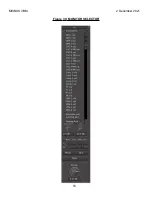
Page 53: ...MIXBUS VBM 2 December 2021 Figure 39 MONITOR SELECTOR 53 ...
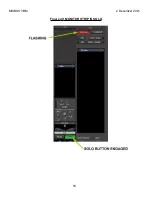
Page 54: ...MIXBUS VBM 2 December 2021 Figure 40 MONITOR STRIP IN SOLO 54 ...
Page 56: ...MIXBUS VBM 2 December 2021 Figure 42 ROUTING TOOL 56 ...
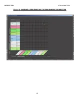
Page 57: ...MIXBUS VBM 2 December 2021 Figure 43 SHOWING A PROGRAM BUS TO PROGRAM BUS CONNECTION 57 ...
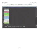
Page 58: ...MIXBUS VBM 2 December 2021 Figure 44 MONITOR STRIP CONNECTION TO EXTERNAL INTERFACE 58 ...
Page 64: ...MIXBUS VBM 2 December 2021 Figure 48 ACE IFB SIDECHAIN INPUT CONNECTION 64 ...
Page 67: ...MIXBUS VBM 2 December 2021 Figure 50 ABOUT WINDOW END OF VBM USER MANUAL 67 ...


