MIXBUS VBM
2 December 2021
2.0
Overview
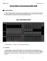
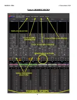
shows the VBM control panel. In the figure left to right, there are 6 basic sections to
the panel.
1.
Input and Bus List
2.
Input Section
3.
VCA Masters
4.
Mix Minus Buses
5.
Program Buses
6.
Monitor Section
The Input and Bus List is selectable and can be hidden if not needed. Additionally, VCA
masters will not be displayed if none have been created.
2.1 Input Section
shows the input section of Mixbus VBM. The input section is comprised of several
channel strips, the number of which is limited only by the amount of your computing power.
Channel strips are added by creating Inputs or Contributors.
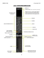
Channel strips may be either mono or stereo. The ones shown in
stereo.
At the top of the input section are 4 buttons. They are:
1.
Template
– This button is used when starting VBM for a new project. It provides a fast
method of configuring a full mixing session based on a preset list of channels and
names. The user can either accept the defaults or modify them as needed. Once ready,
pressing the OK button will create the selected channels in the mixer in one step.
2.
Add Contributor
–
DEFINITION: A "Contributor" is an audio source that has a MixMinus bus corresponding
to its input channel.
This button adds both an input channel and a corresponding MixMinus bus. The
contributor may be either stereo or mono.
3.
Add Input
– This button adds an input channel. The input may be either stereo or
mono. No MixMinus bus corresponding to this input is created.
4.
Add VCA
– This button adds a VCA master. When a VCA master is created, all
channel strips have a VCA assign button added at the bottom. See Section
7
Summary of Contents for Mixbus VBM
Page 1: ...MANUAL VERSION 1 5 DATE 2 December 2021 NOTES For VBM 1 2 release ...
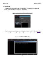
Page 8: ...MIXBUS VBM 2 December 2021 Figure 2 VBM INPUT SECTION 8 ...
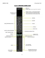
Page 10: ...MIXBUS VBM 2 December 2021 Figure 3 VBM STEREO CHANNEL STRIP 10 ...
Page 11: ...MIXBUS VBM 2 December 2021 Figure 4 VBM MONO CHANNEL STRIP 11 ...
Page 18: ...MIXBUS VBM 2 December 2021 Figure 11 CHANNEL EXTERNAL SEND 18 ...
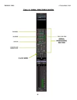
Page 20: ...MIXBUS VBM 2 December 2021 Figure 12 SIGNAL PROCESSING ACCESS 20 ...
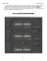
Page 23: ...MIXBUS VBM 2 December 2021 Figure 14 PROGRAM BUS ASSIGN BUTTONS 23 ...
Page 33: ...MIXBUS VBM 2 December 2021 Figure 24 VCA MASTER 33 ...
Page 36: ...MIXBUS VBM 2 December 2021 Figure 27 VBM BUS MASTERS 36 ...
Page 38: ...MIXBUS VBM 2 December 2021 Figure 28 PROGRAM BUS MASTER 38 ...
Page 42: ...MIXBUS VBM 2 December 2021 Figure 31 PROGRAM BUS MASTER SHOWING SENDS SECTION 42 ...
Page 47: ...MIXBUS VBM 2 December 2021 Figure 36 MIX MINUS BUS MASTER 47 ...
Page 51: ...MIXBUS VBM 2 December 2021 Figure 38 VBM MONITOR STRIP 51 ...
Page 53: ...MIXBUS VBM 2 December 2021 Figure 39 MONITOR SELECTOR 53 ...
Page 54: ...MIXBUS VBM 2 December 2021 Figure 40 MONITOR STRIP IN SOLO 54 ...
Page 56: ...MIXBUS VBM 2 December 2021 Figure 42 ROUTING TOOL 56 ...
Page 57: ...MIXBUS VBM 2 December 2021 Figure 43 SHOWING A PROGRAM BUS TO PROGRAM BUS CONNECTION 57 ...
Page 58: ...MIXBUS VBM 2 December 2021 Figure 44 MONITOR STRIP CONNECTION TO EXTERNAL INTERFACE 58 ...
Page 64: ...MIXBUS VBM 2 December 2021 Figure 48 ACE IFB SIDECHAIN INPUT CONNECTION 64 ...
Page 67: ...MIXBUS VBM 2 December 2021 Figure 50 ABOUT WINDOW END OF VBM USER MANUAL 67 ...


