MODU-FIRE
®
Forced Draft Gas-Fired Boiler 2500-3000
37
6. The controller checks that the air pressure switch is open indicating no airflow. The blower is driven towards
the prestart fan speed. When the air pressure switch closes, the 25 second pre-purge time is started. After
the pre-purge, the blower is driven to the ignition speed.
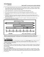
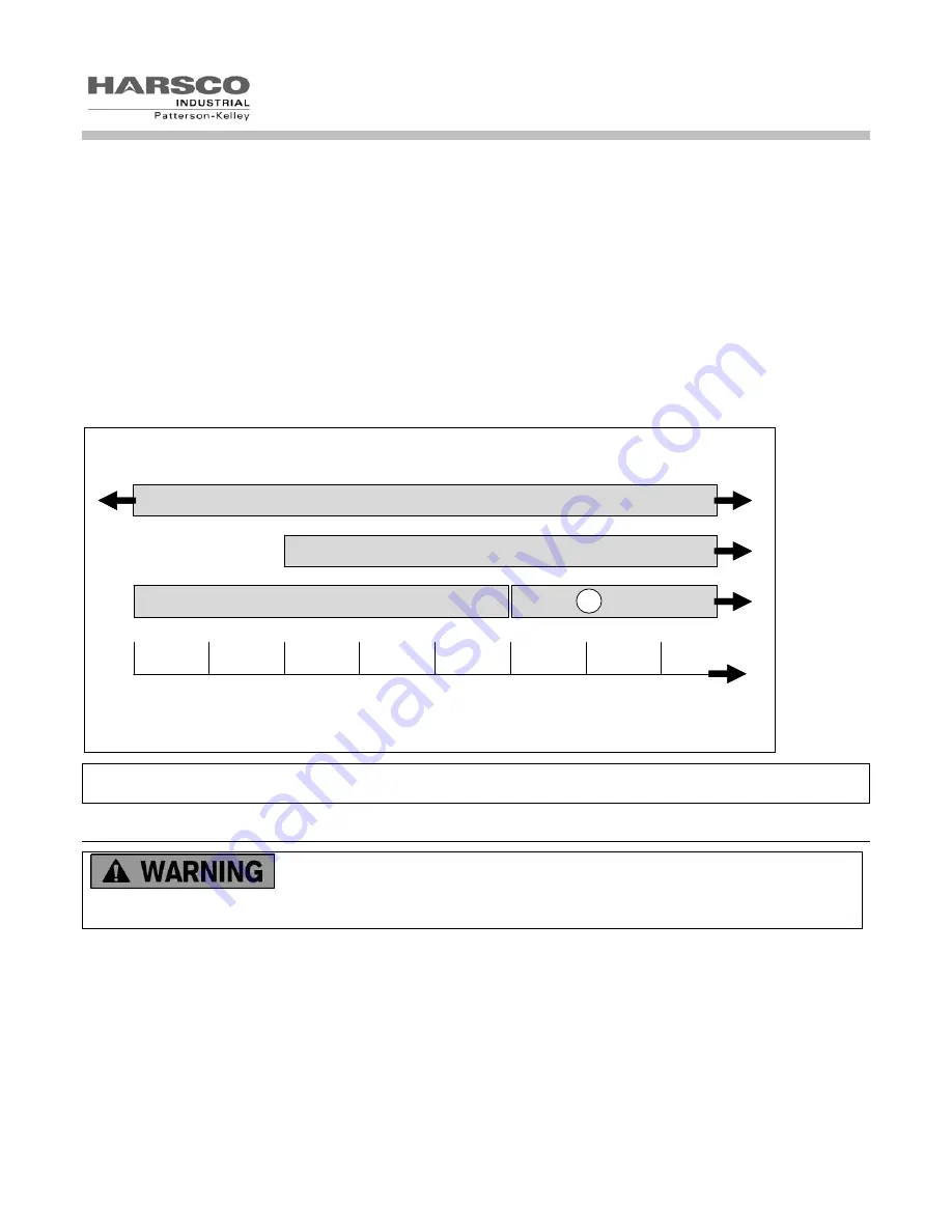
7. A trial for ignition begins. The sequence of events is illustrated graphically below.
8. After ignition, the fan may be driven to low fire before the boiler is released to modulation.
9. The control modulates the firing rate between low and high fire to maintain the desired outlet water
temperature.
10. The burner will continue firing until the outlet water temperature reaches set point plus hysteresis (Off
Differential). At this temperature the fuel supply is shut off and the combustion air fan continues to run for a
30 second post-purge.
11. When the water temperature is reduced by the load on the system, a heat request is generated. The
operating sequence will recycle to step 4.
0
1
2
3
4
5
6
7
Spark
Gas Valve
Flame Detection
Seconds
Fan
*
Flame must be detected at T = 6 seconds
*
Ignition Sequence Timing
0
1
2
3
4
5
6
7
Spark
Gas Valve
Flame Detection
Seconds
Fan
*
Flame must be detected at T = 6 seconds
*
Ignition Sequence Timing
NOTICE! Once the boiler begins the ignition sequence, the firing sequence will continue until main flame is
reached regardless of heat request. The sequence can be interrupted by turning the power switch off.
5.6 T
ROUBLESHOOTING
If any “Manual Reset” limit device trips,
DO NOT RESET
without determining and
correcting the cause. (Manual Reset Limits include: Flame safeguard, high or low gas pressure, high
temperature limit, stack temperature.)
5.6.1
Loss of Power
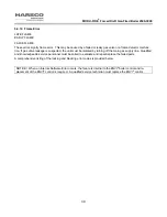
In the event of loss of power, the entire boiler system is de-energized, closing all automatic valves and halting all
boiler operations. When power is restored the sequence of operation will resume at Step 3, provided that all the
limits are satisfied.
5.6.2
Loss of Water Flow
When there is insufficient water flow to close the flow switch, the burner operation is interrupted and the control
displays LOW FLOW / ILK. When water flow is re-established, the sequence returns to Step 3, provided that the
other limits are satisfied. This error also indicates that the interlock jumper is removed or the interlock is wired to
an open device.
Summary of Contents for 1004905923
Page 2: ...MODU FIRE Forced Draft Gas Fired Boiler 2500 3000 2 ...
Page 45: ...MODU FIRE Forced Draft Gas Fired Boiler 2500 3000 45 6 1 3 Wiring Schematic ...
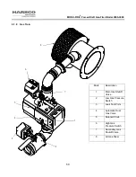
Page 48: ...MODU FIRE Forced Draft Gas Fired Boiler 2500 3000 48 6 1 6 Rear Junction Box ...
Page 49: ...MODU FIRE Forced Draft Gas Fired Boiler 2500 3000 49 6 1 7 Customer Connections ...
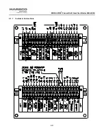
Page 56: ...MODU FIRE Forced Draft Gas Fired Boiler 2500 3000 56 ...

