MODU-FIRE® Forced Draft Gas-Fired Boiler
23
NOTICE! A sediment trap (drip leg) and a union connection should be installed downstream of the
primary manual shutoff valve on the boiler. Gas piping should be installed in accordance with Na-
tional Fuel Gas Code, ANSI Z223.1 and any other local codes which may apply. In Canada, please
refer to CSA-B.149.
3.6.1 Pipe Capacity for Natural Gas
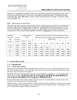
NOTICE! See Pipe Capacity for Natural Gas chart for required pipe size, based on overall length of
pipe from meter plus equivalent length of all fittings. Approximate sizing may be based on 1 cubic
foot of natural gas per 1,000 Btu per hour input, i.e., 500,000 Btu per hour requires about 500 cubic
feet per hour. (See "Typical Boiler Operating Conditions," Section 4.3, for more information.)
Nominal
Iron Pipe
Size
(Inches)
Internal
Diameter
(Inches)
Equivalent Pipe
Length
Maximum Capacity in Cubic Feet of Natural Gas per Hour
Pressure Drop of 0.5 inch Water Column/Equivalent Length of
Pipe (in feet)
90º Ell
(Feet)
Tee
(Feet)
20
40
60
80
100
150
200
1-1/4
1.380
3.45
6.9
950
1-1/2
1.610
4.02
8.04
1,460
990
810
2
2.067
5.17
10.3
2,750
1,900
1,520
1,300
1,150
950
800
2-1/2
2.469
6.16
12.3
4,350
3,000
2,400
2,050
1,850
1,500
1,280
3
3.068
7.67
15.3
7,700
5,300
4,300
3,700
3,250
2,650
2,280
4
4.026
10.1
20.2
15,800
10,900
8,800
7,500
6,700
5,500
4,600
3.7 B
OILER
W
ATER
P
IPING
3.7.1 Piping Design
3.7.1.1 Water Flow in System
Ideal operation of the MODU-FIRE
®
Forced-Draft boiler would consist of a 20º F temperature differential across
the heat exchanger at high fire. Insufficient flow may result in excessive short cycling of the boiler and eventual
damage or premature failure of the equipment.
NOTICE! The closing of the flow switch does not prove that flow is adequate. It only indicates that
some flow is present. Proper flow rates are 60-120 gpm for N750MFD and N1000MFD boilers,
90-150 gpm for N1500MFD and 120-180 gpm for N2000MFD boilers.
Minimum Return Water Temperature should be greater than 130º F to avoid problems of condensation on the
outside of the heat exchanger or in the flue passages.
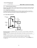
Proper flow rates and return water temperature may be achieved through a combination of primary and secondary
flow loops. Multiple zones and pumps may result in different flow rates at different times. Consideration must be
given to all possible conditions and their consequences.

