GU641A Controller Operation Manual
33
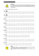
Pre-set 3:
P
(Bar)
0
1.7
3.4
5.2
6.9
8.6
10.3
R
(
Ω
)
21
36
52
72
84
100
120
Pre-set 4:
P
(Bar)
1.0
2.0
3.0
4.0
5.0
6.0
7.0
8.0
9.0
R
(
Ω
)
195
155
127
107
88
72
61
54
48
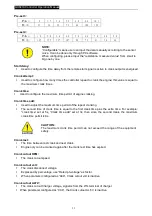
NOTE:
“
Configurable
”
means user can input the data manually according to the sensor
curve. It can be done only through PC software.
When configuring, please input the
“
resistance- measured value
”
from small to
big one by one.
Start delay:
l
Used to configure the time delay from the remote start signal is active to crank output is energised.
Crank attempt:
l
Used to configure how many times the controller repeat to crank the engine; this value is equal to
the maximum crank times.
Crank time:
l
Used to configure the maximum time permit of engine cranking.
Crank time add:
l
Used to adjust the maximum time permit of the repeat cranking.
l
The second time of crank time is equal to the first crank time plus the extra time. For example:
“
crank time
”
set at 5s,
“
Crank time add
”
set at 3s, then since the second crank, the maximum
crank time permit is 8s.
CAUTION:
The maximum crank time permit can not exceed the range of the equipment
safety.
Crank rest:
l
The time between last crank and next crank.
l
Engine only can be cranked again after the crank rest time has expired.
Crank cutout RPM:
l
The crank cutout speed.
Crank cutout volt:
l
The crank disconnect voltage
l
Expressed by percentage, use
“
Rated ph-voltage
”
as factor.
l
When parameter configured as
“
999
”
, Crank cutout volt is inactive.
Crank cutout ALT-V:
l
The crank cutout Charger voltage, signal is from the W/L terminal of charger.
l
When parameter configured as
“
99.9
”
, the Crank cutout ALT-V is inactive.


