background image

6 – English

EXTENSION CORDS

Use only 3-wire extension cords that have 3-prong grounding 
plugs and 3-pole receptacles that accept the product’s plug. 
When using a power tool at a considerable distance from 
the power source, use an extension cord heavy enough to 
carry the current that the product will draw. An undersized 
extension cord will cause a drop in line voltage, resulting in 
a loss of power and causing the motor to overheat. Use the 
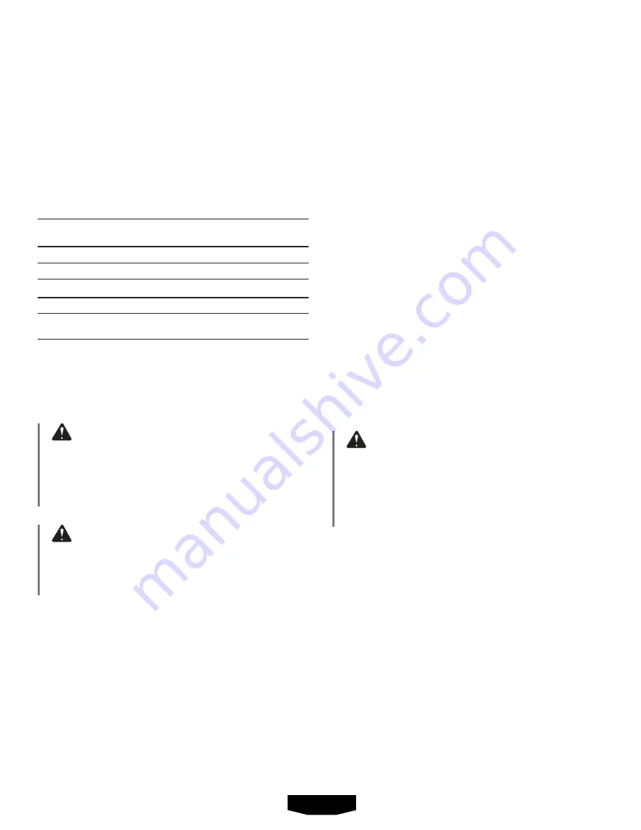
chart provided below to determine the minimum wire size 
required in an extension cord. Only round jacketed cords 
listed by Underwriter’s Laboratories (UL) should be used.

**Ampere rating (on product data plate)


0-2.0 

2.1-3.4 

3.5-5.0  5.1-7.0  7.1-12.0   12.1-16.0

Cord Length   

 Wire Size (A.W.G.)

 25’ 16  16 16 16 14  14
 50’ 16  16 16 14 14  12
 100’ 16  16 14 12 10  —

**Used on 12 gauge - 20 amp circuit.

NOTE:

 AWG = American Wire Gauge

When working with the product outdoors, use an extension 
cord that is designed for outside use. This is indicated by 
the letters “W-A” or “W” on the cord’s jacket. 

Before using an extension cord, inspect it for loose or 

exposed wires and cut or worn insulation.

WARNING:

Keep  the  extension  cord  clear  of  the  working  area.
Position  the  cord  so  that  it  will  not  get  caught  on 

lumber, tools, or other obstructions while you are 

working with a power tool. Failure to do so can result 
in serious personal injury.

WARNING:

Check extension cords before each use. If damaged 
replace  immediately.  Never  use  the  product  with  a 

damaged cord since touching the damaged area could 

cause electrical shock resulting in serious injury.

ELECTRICAL CONNECTION

This product is powered by a precision-built electric motor. 
It should be connected to a power supply that is 120 V, AC 
only (normal household current), 60 Hz. Do not operate this 

ELECTRICAL

product on direct current (DC). A substantial voltage drop 
will cause a loss of power and the motor will overheat. If 

the product does not operate when plugged into an outlet, 

double check the power supply.

SPEED AND WIRING

The no-load speed of this product is approximately 3,500 
rpm. This speed is not constant and decreases under a load 
or with lower voltage. For voltage, the wiring in a shop is as 
important as the motor’s horsepower rating. A line intended 
only for lights cannot properly carry a power tool motor. Wire 
that is heavy enough for a short distance will be too light for 
a greater distance. A line that can support one power tool 
may not be able to support two or three products.

GROUNDING INSTRUCTIONS

See Figure 1, page 11.

This product must be grounded. In the event of a malfunction 
or breakdown, grounding provides a path of least resistance 
for  electric  current  to  reduce  the  risk  of  electric  shock. 
This product is equipped with an electric cord having an 
equipment-grounding conductor and a grounding plug. The 

plug must be plugged into a matching outlet that is properly 
installed and grounded in accordance with all local codes 

and ordinances.
Do not modify the plug provided. If it will not fit the outlet, 
have the proper outlet installed by a qualified electrician. 

WARNING:

Improper connection of the grounding plug can result 

in a risk of electric shock. When repair or replacement 

of the cord is required, do not connect the grounding 

wire to either flat blade terminal. The wire with insulation 
having an outer surface that is green with or without 
yellow stripes is the grounding wire.

Check with a qualified electrician or service personnel if the 

grounding instructions are not completely understood, or 

if in doubt as to whether the product is properly grounded.
Repair or replace a damaged or worn cord immediately.
This product is for use on a nominal 120 V circuit and has 

a grounding plug similar to the plug illustrated in figure 1, 

page 11. Only connect the product to an outlet having the 
same configuration as the plug. Do not use an adapter with 
this product.

Summary of Contents for HTBG01

Page 1: ...icas 7 Armado 7 8 Funcionamiento 8 9 Mantenimiento 10 Illustraciones 11 13 Pedidos de piezas y servicio P g posterior THIS INSTRUCTION BOOKLET CONTAINS IMPORTANT SAFETY INFORMATION PLEASE READ AND KEE...

Page 2: ...If in doubt use the next heavier gauge The smaller the gauge number the heavier the cord Dress properly Do not wear loose clothing gloves neckties or jewelry They can get caught and draw you into mov...

Page 3: ...s Do not use tool if switch does not turn it on and off Have defective switches replaced by an authorized service center Inspect tool cords periodically If damaged have repaired by a qualified service...

Page 4: ...dle shaft is bent Frequently clean grinding dust from beneath grinder Secure long hair so it is above shoulder level to prevent entanglement in any rotating parts Stay alert and exercise control Watch...

Page 5: ...heir meaning Proper interpretation of these symbols will allow you to operate the product better and safer SYMBOL NAME DESIGNATION EXPLANATION Safety Alert Indicates a potential personal injury hazard...

Page 6: ...se a loss of power and the motor will overheat If the product does not operate when plugged into an outlet double check the power supply SPEED AND WIRING The no load speed of this product is approxima...

Page 7: ...teration or modification is misuse and could result in a hazardous condition leading to possible serious personal injury WARNING Do not connect to power supply until assembly is complete Failure to co...

Page 8: ...ers MOUNTING GRINDER TO WORKBENCH See Figure 8 page 12 The bench grinder must be mounted to a firm supporting surface such as a workbench or leg stand Four bolt holes have been provided in the tool s...

Page 9: ...overheat and prematurely wear down the grinding wheel ON OFF SWITCH See Figure 10 page 12 The bench grinder features a front access on off switch for convenience and safety SHARPENING TWIST DRILL BITS...

Page 10: ...ication is required POWER SUPPLY CORD REPLACEMENT If replacement of the power supply cord is necessary this must be done by an authorized service center in order to avoid a safety hazard WHEEL REPLACE...

Page 11: ...orter une tenue appropri e Ne pas porter de v tements amples gants cravate ou bijoux Ces articles pourraient tre happ s et tirer la main ou une partie du corps dans les pi ces en mouvement Les cheveux...

Page 12: ...tateursd fectueuxdansuncentreder parations agr Inspecter r guli rement les cordons de l outil S ils sont endommag s les par un technicien qualifi ou un centre de r parations agr Le fil gaine verte ave...

Page 13: ...ser la meuleuse si l crou de flasque manque ou si l axe de la meule est tordu Nettoyerfr quemmentlapoussi redemeulagedudessous de la machine Attacher les cheveux longs pour les maintenir au dessus des...

Page 14: ...e blessures ou de dommages viter tout contact avec les surfaces b lantes V Volts Tension A Amp res Intensit Hz Hertz Fr quence cycles par seconde W Watt Puissance min Minutes Temps Courant alternatif...

Page 15: ...60 Hz Ne pas utiliser cet produit sur une source de courant continu c c Une chute de tension importante causerait une perte de puissance et une surchauffe du moteur Si l outil ne fonctionne pas une f...

Page 16: ...Ne pas brancher sur le secteur avant d avoir termin l assemblage Le non respect de cet avertissement peut causer un d marrage accidentel entra nant des blessures graves AVERTISSEMENT Toujours faire t...

Page 17: ...plan de travail ferme tel qu un tabli ou un stand Pour ce faire la base de la scie comporte quatre trous Ces quatre trous doivent tre utilis s pour fixer la scie sur le plan de travail au moyen de qu...

Page 18: ...tre l objet aff t NOTE Une pression excessive peut endommager l outil causer la surchauffe du moteur et user pr matur ment la meule INTERRUPTEUR MARCHE ARR T Voir la figure 10 page 12 La meuleuse est...

Page 19: ...ur e de vie de l outil dans des conditions d utilisation normales Aucune autre lubrification n est donc n cessaire REMPLACEMENTDUCORDOND ALIMENTATION S il y a lieu le cordon d alimentation doit tre re...

Page 20: ...i alhajas Podr an engancharse y tirar de usted hacia partes en movimiento Si tiene el pelo largo c braselo para que quede recogido Siempre p ngase anteojos de seguridad con protecci n lateral Los ante...

Page 21: ...e da a la herramienta permita que la repare un t cnico calificado en un centro de servicio autorizado El conductor con aislamiento que tiene una superficie exterior verde con o sin tiras amarillas es...

Page 22: ...el apoyo correspondiente No use la esmeriladora de banco si la tuerca de brida o la tuerca de sujeci n faltan o si est doblado el eje del husillo Limpie frecuentemente el polvo de esmerilado acumulad...

Page 23: ...los le permitir utilizar mejor y de manera m s segura el producto S MBOLO NOMBRE DENOMINACI N EXPLICACI N Alerta de seguridad Indica un peligro posible de lesiones personales Lea el manual del operado...

Page 24: ...je causa la p rdida de potencia y el recalentamiento del motor Si la sierra no funciona al conectarla en una toma de corriente vuelva a revisar el suministro de corriente VELOCIDAD Y CABLEADO La veloc...

Page 25: ...nistro de corriente sin haber terminado de armarla De lo contrario la unidad puede ponerse en marcha accidentalmente con el consiguiente riesgo de lesiones corporales serias ADVERTENCIA Siempre gire c...

Page 26: ...ara bater as Vuelva a colocar y asegure la tapa del compartimiento para bater as MONTAJE DE LA ESMERILADORA EN UN BANCO DE TRABAJO Vea la figura 8 p gina 12 La esmeriladora en un banco debe montarse e...

Page 27: ...presi n excesiva puede da ar la herramienta recalentar el motor y gastar prematuramente la muela abrasiva INTERRUPTOR DE ENCENDIDO APAGADO Vea la figura 10 p gina 12 La esmeriladora de banco dispone...

Page 28: ...Por lo tanto no se necesita lubricaci n adicional REEMPLAZO DEL CORD N DE CORRIENTE Un centro de servicio autorizado deben cambiar el cord n de corriente en caso de que sea necesario para evitar peli...

Page 29: ...e de grain fin muela de grano fino F Work rest knob bouton du appui perilla de apoyo de la pieza de trabajo G Right work rest appui droite apoyo de la pieza de trabajo derecha H Left work rest appui g...

Page 30: ...e chispas con diodo luminiscente D Recessed area zone en retrait rea empotrada E Bolt boulon perno A Bolt boulon perno B Washers rondelles arandelas C Lock washer rondelle de blocage arandela de fijac...

Page 31: ...ieur brida exterior E Grinding wheel meule disque muela abrasiva F Flange nut crou embase tuerca de brida G Inner flange flasque int rieur brida interior H Spindle shaft broche eje del husillo E Wire...

Page 32: ...es du produit Enregistrer le produit https HARTtools com register Les d tails de la garantie sont disponibles sur www HARTtools com Une preuve d achat est requise pour valider la garantie limit e de 3...

Reviews: