VVP10 HART
HART
®
VALVE POSITIONER
INSTALLATION, OPERATION, CONFIGURATION AND MAINTENANCE MANUAL
______________________________________________________________________________________________________________________________
12
2.3.
ELECTRICAL CONNECTION
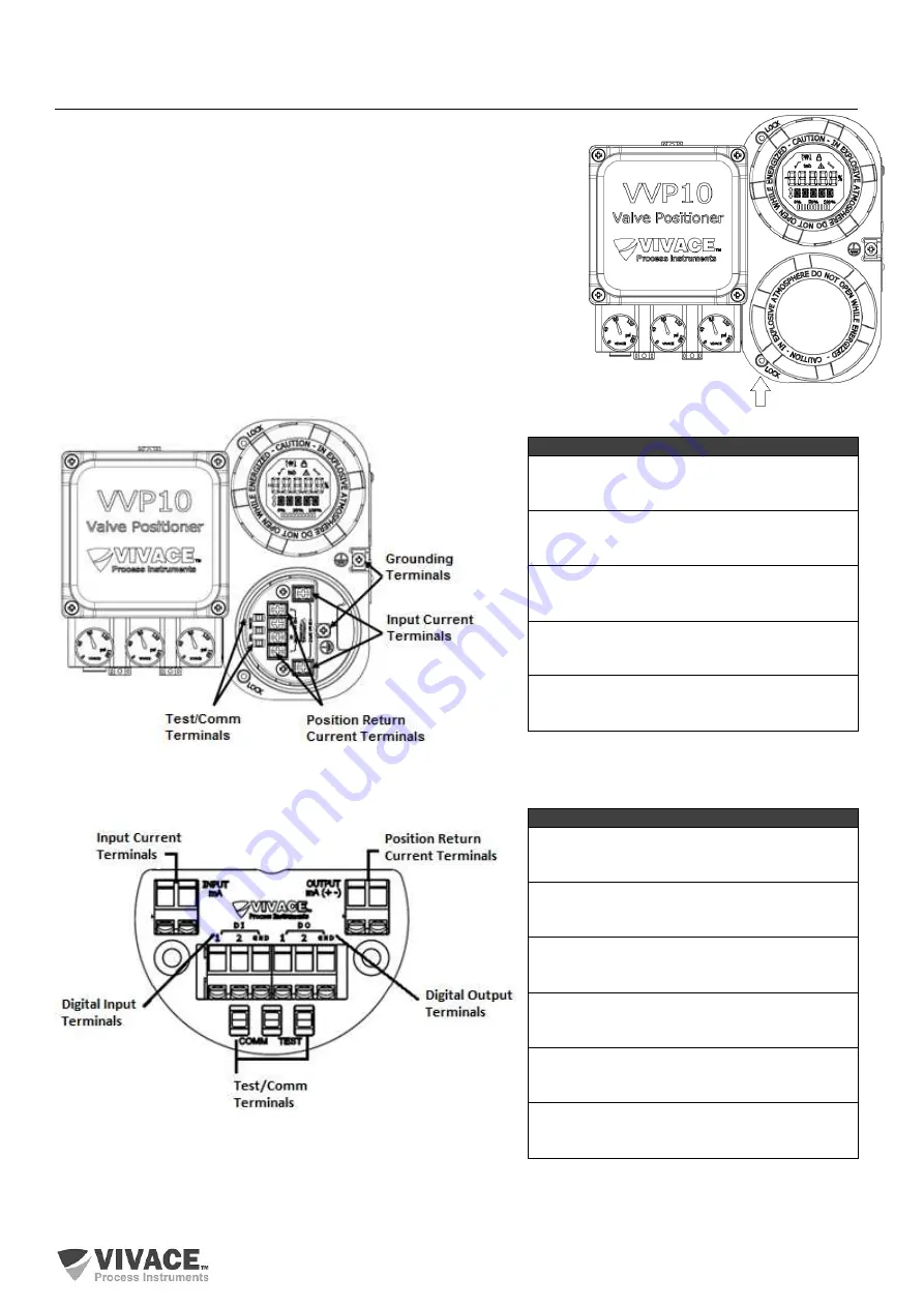
To access the terminal block, remove the blind cover (without display). To
do so, loosen the cover locking screw (see figure 2.10) by turning it
clockwise.
Figure 2.11 shows power terminals, ground terminals (one internal and one
external), plus communication terminals, 4-20 mA current return and tests
for standard VVP10 HART. Figure 2.12 shows terminals for digital I/O model
(complete).
To power the equipment, it is recommended to use twisted-pair 22 AWG
cables. Tables 2.1 and 2.2 describe the functions of the terminals for
standard and complete VVP10 HART models, respectively.
Figure 2.10 – Terminal block cover lock.
Figure 2.11 – Terminal identification for standard VVP10 HART. Table 2.1 – Terminal description for standard model.
Figure 2.12 – Terminal identification for complete VVP10 HART.
Table 2.2 – Terminal description for complete model.
Terminal Description – Standard Model
Power Supply Terminals
4-20 mA INPUT (no polarity)
Position Return Current Terminals
4-20 mA OUTPUT
Grounding Terminals
1 internal and 1 external
Test Terminals - TEST
Loop 4-20 mA without circuit opening
Communication Terminals – COMM
HART
®
Configuration
Terminal Description – Complete Model
Power Supply Terminals
4-20 mA INPUT (no polarity)
Position Return Current Terminals
4-20 mA OUTPUT
Digital Input Terminals
DI (1 - 2) and Ground (GND)
Digital Output Terminals
DO (1 - 2) and Ground (GND)
Test Terminals - TEST
Loop 4-20 mA without circuit opening
Communication Terminals – COMM
HART
®
Configuration


