VVP10 HART
HART
®
VALVE POSITIONER
INSTALLATION, OPERATION, CONFIGURATION AND MAINTENANCE MANUAL
______________________________________________________________________________________________________________________________
43
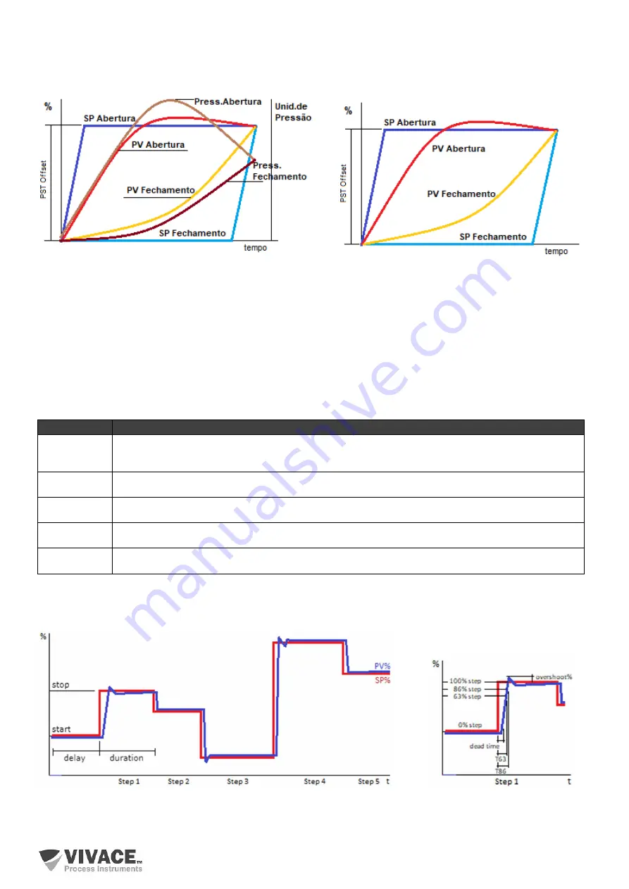
In the graphs of the following figures, we have the example of a curve in a double acting system after the
Partial Stroke
Test
for opening a safety valve (
PST Type = 'Opening'
).
Figure 3.27 – Example of PST ins a double action system Figure 3.28 – Example of PST in a double action system
for a modelo with pressure sensors.
for a model without pressure sensors.
The test stores all Setpoint, Position and Output Pressure (for compatible models) points measured, enabling the user
to save in the personal file the full graph for future comparison.
Step Response Test
Test that checks PID control performance when applying steps set by the user to Setpoint and analyze the system
response. It is performed by the positioner himself, regardless of being connected to some monitoring system. The
user can configure up to ten independent steps as described below.
During the simulation of user-configured steps, the positioner will store the Setpoint and Position points of each step,
for later plotting on the test graph, as exemplified in figure 3.29, which identifies the function of each parameter
configured by the user for Step 1.
Figure 3.29 – Example of Step Response Test with five steps.
Figure 3.30 – Parameters of performance
for step 1.
Parameter
Description
Number of
Steps
It configures the number of Setpoint steps to be simulated during the test (from 1 to 10). The test
starts at step one and goes to the last step configured in this parameter, when it ends.
Start Position
It configures the starting position of that step (in percentage).
Stop Position
It configures the final position of that step (in percentage).
Delay
It configures the waiting time (up to 60s) for the control to adjust to the initial position of that step.
Duration
It configures the duration time (up to 60s) of that step.


