VVP10 HART
HART
®
VALVE POSITIONER
INSTALLATION, OPERATION, CONFIGURATION AND MAINTENANCE MANUAL
______________________________________________________________________________________________________________________________
49
Access to Pneumatic Compartment
1 Remove the top cover (1) through the four cross-head screws;
2 Remove the spool valve assembly (8) through the two allen screws, ensuring that there is an o-ring and gasket
between this assembly and the pneumatic housing (9);
3 Remove the internal pressure regulator assembly (5) by simply unscrewing the complete assembly by the lateral
"flats". Take care not to unscrew by the "flat" of the regulator cover, since there will be access to the regulator
housings;
4 Also note the existence of two o-rings on the lower face of the regulator;
5 Remove the restriction screw (4) by unscrewing it and then pulling it with a pair of pliers. This restriction has a small
diameter hole and is recommended to be cleaned periodically;
6 Remove the I/P - magnetic coil assembly (3) through the two larger allen screws. Do not remove by the three
smaller screws, because, this way, there will be access to the reed and internal of the coil assembly;
7 If you need to calibrate the coil assembly and the regulator assembly, you can remove the calibration plugs (7) and
attach an appropriate device that can be supplied by Vivace to monitor the pressures. Refer to the specific positioner
maintenance manual on the Vivace website if you need to perform this procedure.
Access to Electronic Compartment
1 Remove the electronic housing (23) from the pneumatic housing (9) through the four allen screws. There is a
cylindrical joint between the casings with little diametral clearance, due to the tolerances required by the certification
standards in explosive atmospheres;
2 Remove the signal connection cable (from the display compartment), the Hall sensor power cable and the position
return cable (from the terminal compartment) from the analog plate (14);
3 Remove the analog board (14) from the pneumatic housing through the three cross-slot screws;
4 Check for the existence of three insulating rings under the analog plate, in versions with pressure sensors. Each
has two o-rings to seal the pressures around the sensors on the analog board.
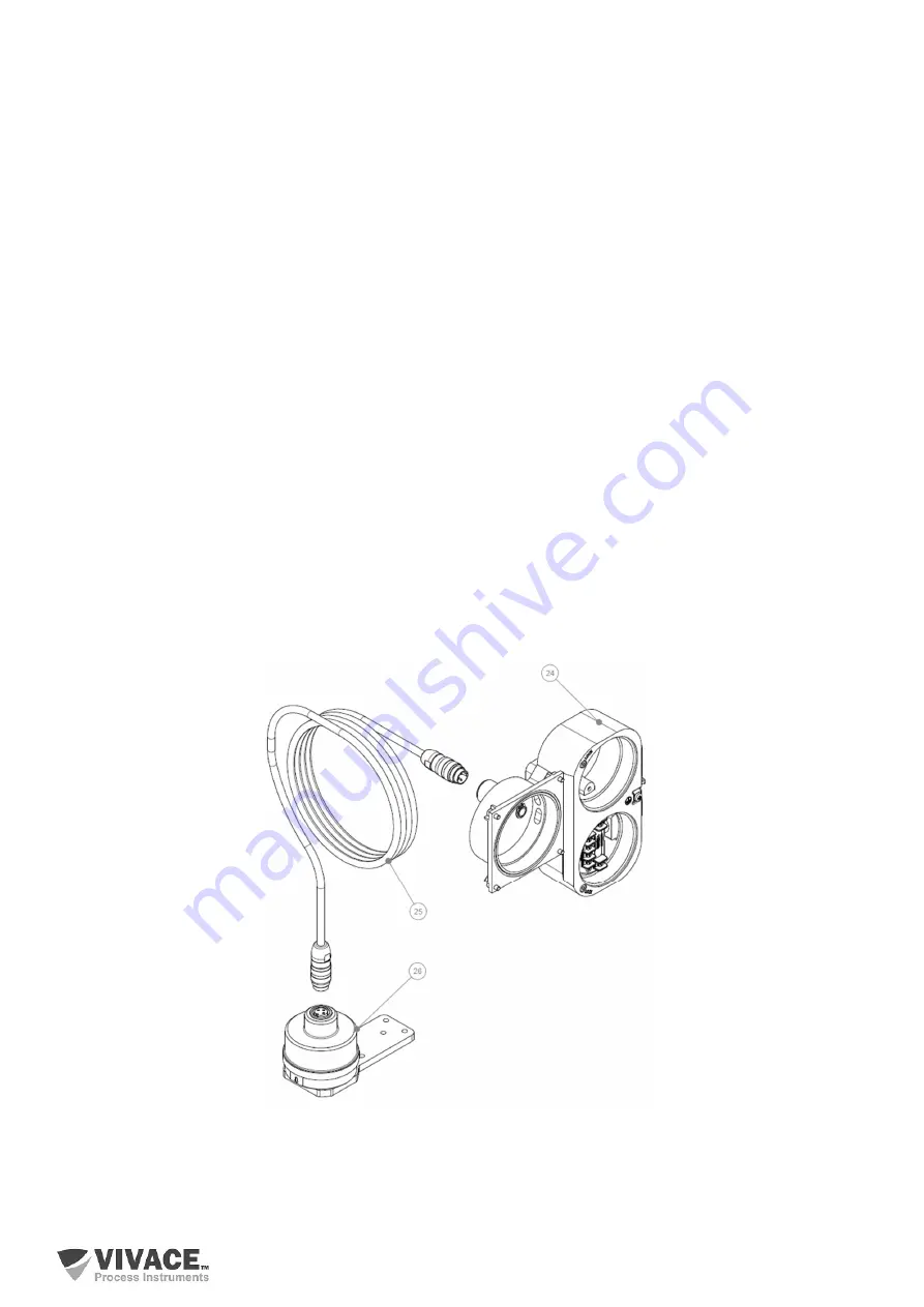
Figure 4.2 shows optional remote sensor components.
Figure 4.2 – Exploded view of VVP10 HART remote sensor.


