17
English
Manual
4. Putting into operation
4.1 Preparations
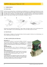
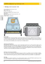
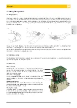
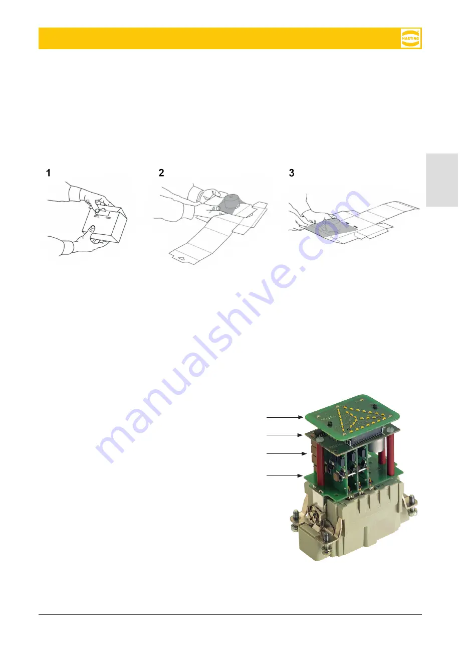
When you receive the product, check that its packaging is undamaged. Open the carton and fold it apart completely
in order to remove the Multiphase Test Connector. Fold the tabs up at the rear end. Then turn it so that the tightened
foil is accessible (as shown in step 2 of the illustration). The foil keeps the Multiphase Test Connector fixed in the
package. The foil becomes loose when you fold up the rear tabs so that the Multiphase Test Connector can easily be
removed from the package.
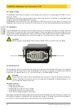
Always inspect the Multiphase Test Connector for external signs of damage before using it. If the Multiphase Test
Connector is not damaged, the cover can be removed and the measurement started.
No special preparations are required for the actual handling of the Multiphase Test Connector. The Multiphase Test
Connector is delivered in a ready-to-use state.
4.2 Initial operation
The Multiphase Test Connector is ready to use as delivered. The user must only remove the cover, before starting
operation. No special assembly is required..
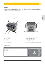
4.3 Structure
1
2
3
4
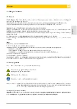
Base board (1)
The Multiphase Test Connector is schematically divided into six
boards. The illustration shows the different boards. The base
board is used to connect the insert interface. This board also
holds the protective fuses.
Converter board(s) (2)
On the converter boards, each phase is converted from the
nominal voltage of 230 V AC to the internal working voltage of
24 V DC.
Evaluation board (3)
The evaluation board contains the electronics for evaluating the
star-delta circuits, clockwise/counter-clockwise rotating field, and
the phase connections (L1, L2, L3).
Display board (4)
The upper part of the display board contains only the LEDs used
to indicate the measured parameters. Light conductors are used
to guide the status display light through the openings in the hous-
ing and outwards to the display.

