16
4.4 Setting Up the System
The system will be set up in the following sequence:
1. Unpack the contents of the shipping box.
2. Check for obvious signs of exterior damage. If damage is
noted, contact BTX Customer Service before proceeding.
3. Place the Waveform Generator on the top of a sturdy table.
4. Connect the electrode cable into the connector at the
bottom right of the front panel.
5. Connect the mains/power cord into the back panel at the
bottom right.
6. Connect the foot switch (if applicable) into one of the USB
ports at the bottom left corner of the Waveform Generator
(front panel).
PLEASE CONTACT BTX IF YOU ARE INTERESTED IN AN ON
SITE TRAINING.
4.4.1 Initial System Test
This section will describe the process to verify mains/line cable
has been installed properly and the computer boots up.
1. Connect the system power cord to the mains.
(Plug in the device)
2. Turn the rocker switch (Line/Main Power) on the front
panel to the “on” position (I).
The rocker switch labeled “Power” should illuminate, and the
Login Screen should appear within 10 seconds. If the Waveform
Generator power switch fails to illuminate, then return it to the
OFF position (O). Verify the power cord is properly plugged into
the wall. Verify the wall socket is functional. If necessary, you
may need to check the fuse on the back panel of the Waveform
Generator. If it is faulty, replace it with the exact type fuse
(240V/5A, slo-blo) 5x20 mm.
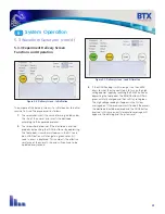
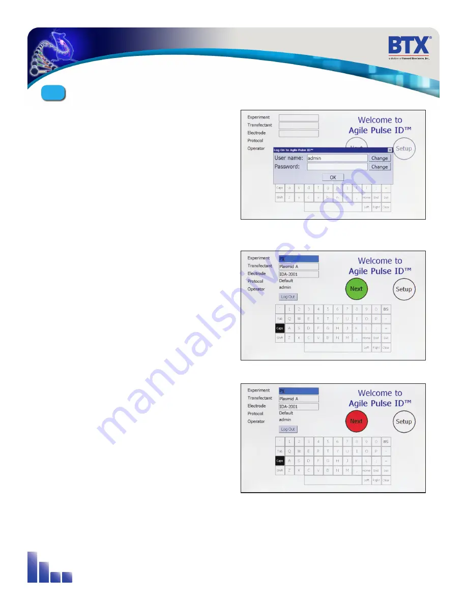
If the power is properly applied, the screen should appear as that
shown in Figure 4-3. After entering the user login information and
tapping “OK”, the software continues its initialization procedure
and the NEXT button will have a white fill.
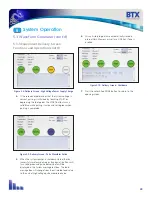
If the internal system checks are successfully completed, the
NEXT button will turn GREEN indicating the system is ready for
use (Figure 4-4). If the NEXT button turns RED, then the internal
checks failed (Figure 4-5). The system cannot be used if the
button is red. Contact BTX Customer Service for assistance.
Figure 4-3: Login Screen
(visible about 10 seconds after power on)
Figure 4-4: System OK Screen (Operating Correctly)
Figure 4-5: Self Check Was Not Successful Screen
AgilePulse
™
System Components & Set-Up
4


