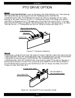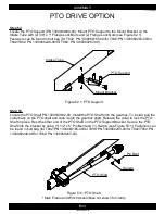
Figure 55.1: Removal of Flangettes and Bearing
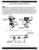
Figure 56.1: Flangettes and Bearing
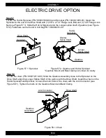
Figure 56.2: Drive Shaft Electric and
Coupler Drive Shaft
B35
ASSEMBLY
1300060439-65-00
ELECTRIC DRIVE OPTION
Step 56
(Only for T836/T862)
Locate the Flangettes (PN 1300010656-00), 1" Bore Bearing (PN
1300010670-00), Drive Shaft Electric (for T836: PN 1300011825-00/for T862: PN 1300011997-00),
and Coupler Drive Shaft (PN 1300010951-00). Mount the Flangettes and 1" Bore Bearing on the Top
Bearing mount bracket onto the Intake Tube with (2) 5/16" x 1" Carriage Bolts and (2) 5/16" Flange
Lock Nuts (see Figure 56.1). Insert the Drive Shaft Electric through the Bearings on Bearing Mount
Brackets on Intake Tube and (for T836: Discharge Tube/for T862: Mid Tube), Connect the Drive Shaft
Electric with the (for T836: Drive Shaft Discharge/for T862: Drive Shaft Mid) using the Coupler Drive
Shaft, (2) 3/8" x 2" Flange Lock Bolts and (2) 3/8" Flange Lock Nuts (see Figure 56.2). Fasteners can
be found in bolt bags (for T836: PN 1300060171-00 and PN 1300060256-00/for T862: PN
1300060269-00 and PN 1300060270-00).
Step 55
(Only for T832)
Remove the (2) Flangettes, (1) 1" Bore Bearing, (2) 5/16" x 1" Carriage Bolts, and (2)
5/16" Flange Lock Nuts from the Discharge Tube Bearing mount bracket (see Figure 55.1).
Intake Tube
Discharge Tube
Bearing Mount Bracket
1" Bore Bearing
Flangette
Drive Shaft
Electric
Drive Shaft
Mid or Discharge
Coupler
Drive Shaft
Intake Tube
Mid or Discharge
Tube
Intake Tube
Flangette
1" Bore Bearing
Bearing Mount Barcket


