background image

Screw, Self Tapping, #12X3/4"

26

1300010304-00

1

Guard Drive Shaft Long T Augers 

4

1300010942-00

2

Tube Discharge T862

1

1300031058-00

3

NUT, HEX, FLANGED, Steel, Mild 3/8-16 UNC

49

13073100006

4

Drive Shaft Discharge T8 T1032/36/42

1

1300010944-00

5

Coupler Drive Shaft T8 T1032/36/42 T1332

2

1300010950-00

6

Flange Lock Bolt 3/8 x 2-16    Gr 5

8

13071206032

7

BOLT, HEX, FLANGED, Steel, Mild 3/8-16 UNC X 1

25

13071206016

8

Stover Locknut 1/2-13 Type B Gr 5

6

13073000008

9

Hex Cap Screw 1/2 x 2 1/2-13   Gr 5 

6

13070208040

10

Flight Discharge T8

1

1300030895-00

11

Track Angles Upper T862 T1062

1

1300030979-00

12

BOLT, CARRIAGE 3/8-16 UNC x 1  Steel, Mild

20

13070906016

13

Stop Track T862 T1062

1

1300011698-00

14

Carriage Bolt 5/16 x 1-18  Gr 5

26

13070905016

15

Flangette 2 Bolt 1" Bearing

26

1300010656-00

16

Bearing 1" D Roller w/ Lock Collar T8/10/13 

13

1300010670-00

17

Flange Lock Nut 5/16-18  Gr 5

26

13073100005

18

Flange Lock Bolt 1/2 x 1 1/2-13 Gr 5

4

13071208024

19

Gasket Bearing Discharge T8

1

1300011439-00

20

Bearing - 1 1/4" c/w F207 Housing

1

13000006731-00

21

Flange Lock Nut 1/2-13  Gr 5

4

13073100008

22

Drive Shaft Mid T852/62

1

1300011878-00

23

Stover Locknut 5/8-11 Type B   Gr 5

1

13073000010

24

Hex Cap Screw 5/8 x 3 3/4-11   Gr 5

1

13070210060

25

Stop Track T8/10/13 

1

1300010959-00

26

Track Angles Lower T862 T1062

1

1300030977-00

27

Tube Mid T862

1

1300031056-00

28

Flight 20' Section T842/52/62

2

1300030917-00

29

Mount Gearbox T8

1

1300032048-00

30

Tube Intake T862

1

1300060268-00

31

Flight  Infeed  T842/52/62

1

1300031010-00

32

Nylon Locknut 3/8-16   Gr 5

4

13072900006

33

Band Clamp 10 Ga T8

1

1300013280-00

34

Brakewinch Auto 1.5K Capacity 1 Speed

1

1300030108-00

35

C17

PARTS

1300060439-05-00

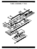
TUBE ASSEMBLY T862

1

1

2

1

2

4

6

7

8

5

3

22

21

20

19

18

17

16

15

8

14

4

13

4

12

10

9

11

9

10

1

2

1

2

23

4

7

6

8

24

25

4

26

8

4

13

27

9

10

9

10

29

7

30

31

8

35

4

4

34

33

9

10

29

9

10

32

4

28

Summary of Contents for T8 SERIES

Page 1: ...SAFETYAND OPERATIONSMANUAL SwingMAX ASSEMBLY AND PARTS MANUAL T8 SERIES AUGER T832 T836 T842 T852 T862 ...

Page 2: ...r Harvest by Meridian Inc PO Box 1996 2800 Pasqua Street North Regina Sk Canada S4P 3E1 Declare the Augers listed below conform to the 2006 42 EC Machinery Directive T832 T836 T842 T852 T862 The Harvest by Meridian T Auger is designed for the movement of Grains and Cereals ...

Page 3: ...ption B34 Electric Drive Option B42 Guard Assembly PARTS C1 Frame T832 C3 Frame T836 T842 C5 Frame T852 C7 Frame T862 C9 Tube Assembly T832 C11 Tube Assembly T836 C13 Tube Assembly T842 C15 Tube Assembly T852 C17 Tube Assembly T862 C19 Truss Assembly T852 C21 Truss Assembly T862 C23 Winch Cable Assembly T8 C25 Discharge Head T832 T836 T842 C27 Discharge Head T852 C29 Discharge Head T862 C31 Fork T...

Page 4: ...1300060439 33 00 SIGN OFF SHEET As a requirement of OSHA it is necessary for the employer to train the employee in the safe operation and safety procedures with this equipment We include this sign off sheet for your convenience and personal record keeping ...

Page 5: ... 00 T832 INTAKE TUBE 1300060194 00 TUBE ASSEMBLY 1300031172 00 T836 INTAKE TUBE 1300060195 00 TUBE ASSEMBLY 1300031164 00 T842 INTAKE TUBE 1300060234 00 TUBE ASSEMBLY 1300031192 00 T852 INTAKE TUBE 1300060268 00 TUBE ASSEMBLY 1300031198 00 T862 MID TUBE 1300031053 00 TUBE ASSEMBLY 1300031193 00 T852 ...

Page 6: ...MID TUBE 1300031056 00 TUBE ASSEMBLY 1300031199 00 T862 DISCHARGE TUBE 1300030893 00 TUBE ASSEMBLY 1300031165 00 T832 T836 T842 DISCHARGE TUBE 1300031055 00 TUBE ASSEMBLY 1300031194 00 T852 DISCHARGE TUBE 1300031058 00 TUBE ASSEMBLY 1300031200 00 T862 ...

Page 7: ...Intake and Discharge Tubes Align flighting as shown in Figure 3 1 to make continuous Connect the flighting using 2 1 2 x 2 1 2 Hex Bolts and 2 1 2 Stover Lock Nuts see Figure 3 1 Slide the Intake and Discharge Tubes and put together connect them with 8 3 8 x 1 Flange Lock Bolts and 8 3 8 Flange Lock Nuts see Figure 3 1 Step 2 Place tubes on assembly stands Place stands 12 or less from the end of t...

Page 8: ...Mid Tube with 8 3 8 x 1 Flange Lock Bolts and 8 3 8 Flange Lock Nuts see Figure 4 2 Repeat the steps to connect the Mid and Discharge Tubes as well Step 5 Only for T1052 Locate the Flangettes PN 1300010656 00 the 1 Bore Bearings PN 1300010670 00 Drive Shaft Mid PN 1300011878 00 and bolt bags PN 1300060259 00 and PN 1300060263 00 Attach 6 Flangettes and 3 1 Bore Bearings on the Mid Tube with 6 5 16...

Page 9: ... for T1062 PN 1300060275 00 Connect the Drive Shaft Mid and the Drive Shaft Discharge using the Drive Shaft Coupler 2 3 8 x 2 Flange Lock Bolts and 2 3 8 Flange Lock Nuts see Figure 6 1 Drive Shaft Mid Drive Shaft Discharge Drive Shaft Coupler Step 7 Only for T862 Locate the bolt bag PN 1300060270 00 Connect the Upper Track Angle to the Mid Tube with 2 3 8 x 1 Carriage Bolts and 2 3 8 Flange Lock ...

Page 10: ... of the Discharge Tube with for T852 8 3 8 x 1 Carriage Bolts and 8 3 8 Flange Lock Nuts for T862 12 3 8 x 1 Carriage Bolts and 12 3 8 Flange Lock Nuts see Figure 8 1 Attach the Truss Support to the Truss Uprights with 2 3 8 x 1 Carriage Bolts and 2 3 8 Flange Lock Nuts see Figure 8 2 Step 9 Only for T852 T862 Locate the Truss Adjust Mount Brackets PN 1300030976 00 Mount the Truss Adjust Mount Bra...

Page 11: ...ach 2 1 2 x 6 1 4 Eyebolts and 4 1 2 Hex Lock Nuts to the Left and Right Truss Cable Mount Brackets on the Intake and Mid Tube connection see Figure 10 1 Do not tighten the bolts right now Attach 2 1 2 x 6 1 4 Eyebolts and 4 1 2 Hex Lock Nuts to the Truss Adjust Mount Brackets see Figure 10 2 Attach 2 the Quick Links to the both side of discharge end of the Discharge Tube see Figure 10 3 Attach 2 ...

Page 12: ...r T852 5 16 Cable Clamps for T862 3 8 Cable Clamps see Figure 11 2 Aways have saddles of the Cable Clamps on the live end of the Cable as shown in figure 11 3 Secure the other end of the Truss Cable with the Quick Link at Mid and Discharge Tubes connecton using 2 for T852 5 16 Cable Clamps for T862 3 8 Cable Clamps see Figure 11 4 To tighten the cables lifting the Discharge end of the tubes is req...

Page 13: ... using 2 for T852 5 16 Cable Clamps for T862 3 8 Cable Clamps see Figure 12 2 Aways have saddles of the Cable Clamps on the live end of the Cable as shown in figure 12 3 Secure the other end of the Truss Cable with the Quick Link at Discharge End using 2 for T852 5 16 Cable Clamps for T862 3 8 Cable Clamps see Figure 9 3 To tighten the cables lifting the Discharge end of the tubes is required Plac...

Page 14: ...ach the Fork Bushing to the Fork Housing with 4 3 8 x 1 Hex Bolts and 4 3 8 Flange Lock Nuts see Figure 13 1 Step 14 Locate the Fork Bearing Stub PN 1300010282 00 Insert the Fork Bearing Stub into the Intake Tube Flighting secure it with 1 1 2 x 2 1 2 Hex Bolt and 1 1 2 Stover Lock Nut see Figure 14 1 Fasteners can be found in bolt bag PN 1300060266 00 Fork Housing Fork Bushing Intake Tube Fork Be...

Page 15: ...sing with key stock welded to the bottom of the Intake Tube see Figure 15 1 Secure the Fork Housing assembly on the Intake Tube with 4 3 8 x 1 1 4 Hex Bolts and 4 3 8 Flange Lock Nuts see Figure 15 2 Fasteners can be found in bolt bag PN 1300060266 00 Step 16 Locate the Hitch PN 1300030891 00 Slide the Hitch into the Fork Housing Assembly slide channels and secure it with 2 1 2 x 5 Pins and 2 Hair...

Page 16: ...t see Figure 17 1 Mount the Circular Flangettes and 1 Bore Bushing to the Hopper Pan with 3 3 8 x 1 Hex Bolts see Figure 17 2 Step 18 Locate the Hopper Rubber PN 1300011229 00 Plates Rubber Hopper PN 1300011235 00 and bolt bag PN 1300060081 00 Attach the Hopper Rubber to the Hopper assembly with 29 1 4 x 3 4 Flange Lock Bolts and 29 1 4 Flange Lock Nuts Connect the both end of the Hopper Rubber us...

Page 17: ... the Transition Flight on the Hopper Flight and align key slots secure it with 1 1 4 x 1 4 x 1 1 2 Key 1 5 16 x 1 1 4 Socket Screw and 1 5 16 Flange Lock Nuts see Figure 19 1 Fasteners can be found in bolt bag PN 1300060250 00 Hopper Flight Transition Flight Step 20 Slide in the Flighting Assembly into the Hopper Assembly Align the Hopper Flight and 1 Bore Bushing see Figure 20 1 1 Bore Bushing Ho...

Page 18: ...with the Hopper Throat using 2 3 8 x 1 1 4 Flange Lock Bolts and 2 3 8 Flange Lock Nuts see Figure 21 1 Do not tighten the nuts since they need to be removed to connect the Tube Connection Hopper Hopper Throat Assembly Hopper Assembly Step 22 Locate bolt bag PN 1300060062 00 Connect the Hopper Throat Assembly to the Hopper Assembly with 2 1 2 x 1 1 2 Carriage Bolts 2 1 2 Flat Washers and 2 1 2 Sto...

Page 19: ...Fasteners can be found in bolt bag PN 1300060250 00 Step 24 Locate the Hopper Clamp PN 1300030912 00 Slide the Hopper Clamp onto the Intake Tube and align the slot in the bottom of the Hopper Clamp with key stock welded to the bottom of the Intake Tube see Figure 24 1 secure it with 4 3 8 x 1 1 2 Flange Lock Bolts and 4 3 8 Flange Lock Nuts see Figure 24 2 Do not tighten the nuts yet Fasteners can...

Page 20: ...f the Hopper Throat and align the Stub Transition Hopper Hanger Flight Hopper and Transition Flight Slide the Stub Transition Hopper through the Hanger Flight Hopper and insert into the Transition Flight end Secure it using 1 1 4 x 1 4 x 1 1 2 Key 1 5 16 x 1 1 4 Socket Screw and 1 5 16 Flange Lock Nuts see Figure 26 1 Close the door on the Hopper Throat Connect the Tube Connection Hopper to the Ho...

Page 21: ...Hex Bolt and 1 Stover Lock Nut see Figure 27 2 Connect the other end of the Stop Transport to the tabs on the Tube Connection Hopper with 1 1 2 x 3 1 2 Clevis Pin c w 1 Cotter Pin and 1 1 2 x 5 Pin Bent c w 1 Hairpin see Figure 27 2 Fasteners can be found in bolt bag PN 1300060062 00 Step 28 Locate the Hitch PN 1300030987 00 and bolt bag PN 1300060067 00 Slide the Hitch into the Hopper Assembly sl...

Page 22: ...36 T842 1300030750 00 Main Frame x2 T832 1300030731 00 T836 1300030994 00 T842 1300030753 00 A Frame x2 T832 1300030732 00 A Frame x2 T836 1300030995 00 T842 1300030754 00 Brace Frame x2 T836 T842 1300010988 00 Trolley Roller 1300030733 00 Housing Trolley 1300010929 00 Hub Spindle 1300030730 00 ...

Page 23: ...0 A Frame x2 T852 1300030762 00 T862 1300030970 00 Brace Cross x4 1300010693 00 Trolley Roller T852 1300030733 00 T862 1300030971 00 Housing Trolley T852 1300010929 00 T862 1300011673 00 Arm Anti Twist x2 1300011288 00 Link Anti Twist x2 1300011289 00 Main Frame Right T862 1300030972 00 Main Frame Left T862 1300031012 00 Hub Spindle T1052 1300030730 00 T1062 1300030084 00 ...

Page 24: ...d 4 1 4 Flange Lock Nuts for T836 T842 T852 4 1 2 x 1 1 4 Flange Lock Bolts and 4 1 4 Flange Lock Nuts see Figure 29 1 Attach the Main Frame arms to the Axle and connect the Main Frame Arms Axle and Hub Spindles using 4 1 2 x 1 1 2 Flange Lock Bolts and 4 1 2 Flange Lock Nuts see Figure 29 2 Step 30 Only for T862 Locate the Right and Left Main Frame Arms Axle Hub Spindle PN 1300030084 00 and bolt ...

Page 25: ...ist Arms to the Left and Right Main Frame Arms with 2 3 4 x 1 3 4 Hex Bolts and 2 3 4 Stover Lock Nuts see Figure 31 1 Do not tighten the nuts as they need to be removed to connect the Main Frame Arms with the Intake Tube Attach the Anti Twist Links to the Left and Right Main Frame Arms with 2 1 2 x 1 Flange Lock Bolts and 2 1 2 Flange Lock Nuts see Figure 31 1 Connect the Anti Twist Arms and Anti...

Page 26: ...Locate the tire for T832 T1836 T842 PN 13000005448 00 for T852 T862 PN 1300030103 00 and bolt bag PN 1300060180 00 Attach the A Frame Arms to the Axle with 2 for T832 T836 T842 T852 3 4 x 1 3 4 Hex Bolts for T862 1 x 2 Hex Bolts and 2 for T832 T836 T842 T852 3 4 Stover Lock Nuts for T862 1 Stover Lock Nuts see Figure 33 1 Do not overtighten nuts as the A Frame Arms need to be able to rotate about ...

Page 27: ...sing Trolley and Trolley Roller Attach the Housing Trolley and Trolley Roller to A Frame Arms with 1 for T832 T836 T842 T852 3 4 x 6 1 2 Hex Bolt for T862 1 x 8 Hex Bolt 2 for T832 T836 T842 T852 3 4 Flat Washers for T862 1 Flat Washers and 1 for T832 T836 T842 T852 3 4 Stover Lock Nut for T862 1 Stover Lock Nut see Figure 35 1 Fasteners can be found in bolt bag for T832 PN 1300060175 00 for T836 ...

Page 28: ... 00 and bolt bag for T1052 PN 1300060263 00 for T1062 PN 1300060270 00 For T1052 attach the Stop Track under the Track Angle Short at lower end with 2 3 8 x 1 Flange Lock Bolts and 2 3 8 Flange Lock Nuts see Figure 34 1 For T1062 attach the Stop Track under the Track Angle Lower on the Mid Tube with 2 3 8 x 1 Flange Lock Bolts and 2 3 8 Flange Lock Nuts see Figure 34 2 Mid Tube Track Angle Short T...

Page 29: ...852 Attach the Stop Track on the top end of the Track Angle to restrict the Sliding movement of the A Frame Assemby with 2 3 8 x 1 Flange Lock Bolts and 2 3 8 Flange Lock Nuts see Figure 39 1 for T832 T852 bolt the Stop Track onto the Track Angle using the top set of holes for T836 bolt the Stop Track onto the Track Angle using the 2nd set of holes T842 bolt the Stop Track onto the Track Angle usi...

Page 30: ...11 00 for T852 T862 PN 1300060205 00 Step 41 Lift the Main Frame Arms and attach it to the Main Frame Arms Mount Bracket welded on bottom of the Intake Tube with 2 3 4 x 1 1 2 Hex Bolts and 2 3 4 Stover Lock Nuts see Figure 32 1 Do not overtighten nuts as the Main Frame Arms need to be able to rotate about the bolts The augur should now be up on the Frame Assembly Fasteners can be found in bolt ba...

Page 31: ...Long with 2 3 8 x 1 Flange Lock Bolts and 2 3 8 Flange Lock Nuts see Figure 44 2 Step 43 Locate the winch PN 1300030108 00 and bolt bag for T832 PN 1300060171 00 for T836 PN 1300060171 00 for T842 PN 1300060172 00 for T852 PN 1300060259 00 for T862 PN 1300060269 00 Mount the winch onto the winch mount bracket welded at bottom of the Intake Tube with 3 3 8 x 1 Flange Lock Bolts and 3 3 8 Flange Loc...

Page 32: ... the clamp plate on outer plate Pull the cable 2 outside from the clamp plate and tighten the bolt on the Clamp plate Route the cable up around the Trolley Roller going from the bottom around the top see Figure 45 1 Next pull the cable to the bottom of the discharge tube and wrap the cable around the cable guide for T852 T862 wrap the cable around the 5 8 x 3 3 4 Hex Bolt on Mid Tube Track Angle S...

Page 33: ...t stays in right side of the Gearbox Mount Place the Gearbox Assembly on the Intake Tube and attach the Band Clamp at the bottom of the Gearbox Mount with 4 3 8 x 2 Flange Lock Bolts and 4 3 8 Nylon Lock Nuts see Figure 46 2 Do not tighten the bolts Gearbox Assembly might need to move a bit to connect the gearbox with the Drive Shaft Location of the Gearbox Mount and Band Clamp varies for the diff...

Page 34: ... Drive Shaft 2 3 8 x 2 Flange Lock Bolts and 2 3 8 Flange Lock Nuts see Figure 48 1 Step 47 Only for T836 T842 T852 T862 Locate the Flangettes PN 1300010656 00 the 1 Bore Bearings PN 1300010670 00 and bolt bag for T836 PN 1300060283 00 for T842T852 PN 1300060246 00 for T862 PN 1300060267 00 Attach for T836 4 Flangettes and 2 1 Bore Bearings on the Intake Tube with 4 5 16 x 1 Carriage Bolts and 4 5...

Page 35: ...to the shorter spline shaft of gearbox see Figure 49 2 Fasteners can be found in bolt bag PN 1300060231 00 Step 50 Locate the Chain PN 1300012513 00 Slide the Gearbox Assembly close to the Sprocket on the Drive Shaft PTO align the Shorter Spline Shaft of the gerbox with the Drive Shaft PTO Install the chain on the Hub Sprocket and Sprocket connect the both ends of the chain with the Link Connector...

Page 36: ... bag for T832 PN 1300060165 00 for T836 PN 1300060283 00 for T842 T852 PN 1300060246 00 for T862 PN 1300060267 00 Attach the Housing Guard to the gearbox with 4 5 16 x 1 2 Hex Bolts and 4 Lock Washers see Figure 51 1 Attach the Rubber Shield to the Housing Guard with 6 1 4 x 3 4 Flange Lock Bolts and 4 1 4 Flange Lock Nuts see Figure 52 2 Housing Guard Gearbox Rubber Shield Housing Guard ...

Page 37: ...et Secure the PTO Shaft into the bracket by using 1 1 2 x 5 Pin Bent and 1 Hairpin see Figure 53 1 Fasteners can be found in bolt bag for T832 PN 1300060165 00 for T836 PN 1300060283 00 for T842 T852 PN 1300060246 00 for T862 PN 1300060267 00 Step 52 Locate the PTO Support PN 1300030609 00 Mount PTO Support to the Mount Bracket on the Intake Tube with 2 3 8 x 1 Flange Lock Bolts and 2 Flange Lock ...

Page 38: ...pline shaft stays in left side of the Gearbox Mount Place the Gearbox Assembly on the Intake Tube and attach the Band Clamp at the bottom of the Gearbox Mount with 4 3 8 x 2 Flange Lock Bolts and 4 3 8 Nylon Lock Nuts see Figure 54 2 Do not tighten the bolts Gearbox Assembly might need to move a bit to connect the gearbox with the Drive Shaft Location of the Gearbox Mount and Band Clamp varies for...

Page 39: ...Bearing Mount Brackets on Intake Tube and for T836 Discharge Tube for T862 Mid Tube Connect the Drive Shaft Electric with the for T836 Drive Shaft Discharge for T862 Drive Shaft Mid using the Coupler Drive Shaft 2 3 8 x 2 Flange Lock Bolts and 2 3 8 Flange Lock Nuts see Figure 56 2 Fasteners can be found in bolt bags for T836 PN 1300060171 00 and PN 1300060256 00 for T862 PN 1300060269 00 and PN 1...

Page 40: ...ket connect the both ends of the chain with the Link Connector see Figure 58 1 Tighten the bolts on the Gearbox Mount and Band Clamp Step 57 Locate the Hub Sprocket PN 1300031686 00 and Sprocket PN 1300031685 00 Mount the Sprocket to the end of the Drive Shaft with 1 3 8 x 2 1 4 Flange Lock Bolt and 1 3 8 Flange Lock Nut see Figure 57 1 Slide the Hub Sprocket onto the Longer spline shaft of gearbo...

Page 41: ...to the Frame Motor Mount and Motor Slide Bracket with 6 5 8 Flange Lock Nuts see Figure 60 2 Do not tighten the nuts Fasteners can be found in bolt bag for T832 T842 T852 PN 1300060254 00 for T836 PN 1300060282 00 for T862 1300060254 00 Step 59 Locate the Motor Mount Clamps PN1300030613 00 and bolt bag for T832 T842 T852 PN 1300060254 00 for T836 PN 1300060282 00 for T862 1300060254 00 Mount the M...

Page 42: ...ctric Motor see Figure 62 2 Electric Motor and Lower Pulley are not supplied with the augur and must be purchased separately They are just shown for clarity Fasteners can be found in bolt bag for T832 T842 T852 PN 1300060254 00 for T836 PN 1300060282 00 for T862 1300060254 00 Step 61 Mount Frame Motor Mount Assembly to the Motor Mount Clamps with 8 3 8 x 1 1 4 Flange Lock Bolts and 8 3 8 Flange Lo...

Page 43: ...t Guard Mount with 6 5 16 x 3 4 Flange Lock Bolts and 6 5 16 Flange Lock Nuts see Figure 64 1 Fasteners can be found in bolt bag for T832 T842 T852 PN 1300060254 00 for T836 PN 1300060282 00 for T862 1300060254 00 Step 63 Locate the Belt Guard Mount PN 1300010818 00 Attach the Belt Guard Mount to the gearbox with 4 5 16 x 1 2 Hex Bolts and 4 5 16 Lock Washers see Figure 63 1 Fasteners can be found...

Page 44: ...t down to the Lower Pulley see Figure 66 1 Tighten the Drive Belt by tightening the nuts on the threaded rods Step 65 Locate the Upper Pulley PN 18345 00 and Hub PN 1300010358 00 Place the Upper Pulley on the gearbox drive shaft Slide the Hub on the gearbox drive shaft and secure the hub with the pulley using 2 1 4 x 3 4 Hex Bolts and 2 1 4 Lock Washers see Figure 65 1 Fasteners can be found in bo...

Page 45: ...e 68 1 Fasteners can be found in bolt bag for T832 T842 T852 PN 1300060254 00 for T836 PN 1300060282 00 for T862 1300060254 00 Step 67 Locate the Belt Guard End Short PN 1300010821 00 and Belt Guard End Long PN 1300010820 00 Attach the Belt Guard End Short to the Belt Guard Inner with 2 5 16 x 3 4 Flange Lock Bolts and 2 5 16 Flange Lock Nuts see Figure 67 1 Attach the Belt Guard End Long to the B...

Page 46: ... 4 Self Tapping Screws for T842 18 12 x 3 4 Self Tapping Screws for T852 24 12 x 3 4 Self Tapping Screws for T862 PTO Drive Option 34 12 x 3 4 Self Tapping Screws for T862 Electric Drive Option 24 12 x 3 4 Self Tapping Screws see Figure 70 1 Step 69 Locate the Cover Chain Coupler PN 1300012529 00 Place the Cover Chain Coupler onto the gearbox and secure it with 4 1 2 X 1 Hex Bolts and 4 1 2 Lock W...

Page 47: ...rt over the Guard Drive Shaft Long and slide it under the Cover Chain Coupler Secure it with 2 12 x 3 4 Self Tapping Screws see Figure 71 1 Secure the Guard Drive Shaft Short on Bearing Mount Bracket with for T832 PTO Drive Option 2 12 x 3 4 Self Tapping Screws for T836 PTO Drive Option 6 12 x 3 4 Self Tapping Screws for T836 Electric Drive Option 4 12 x 3 4 Self for T842 T852 PTO Drive Option 2 1...

Page 48: ...80 00 This will complete the assembly for your Harvest by Meridian T832 36 42 52 62 Auger For additional part numbers information overall views please refer to the parts book drawings located at the end of this assembly manual ...

Page 49: ...C1 PARTS 1300060439 11 00 FRAME T832 1 2 3 2 4 5 6 7 8 9 9 1 10 1 11 10 12 13 14 15 16 1 10 12 17 14 ...

Page 50: ...0010304 00 7 Zip Tie 18 2 13000007601 00 8 A Frame T832 T1032 2 1300030732 00 9 Hex Cap Screw 3 4 x 1 1 2 10 Gr 5 4 13070212024 10 Axle T832 T1032 1 1300030729 00 11 Flange Lock Nut 1 2 13 Gr 5 8 13073100008 12 Hub Spindle T832 36 42 52 T1032 36 42 52 2 1300030730 00 13 Flange Lock Bolt 1 2 x 1 1 2 13 Gr 5 8 13071208024 14 Tire ST175 80R13 c w 5 Blt Rim White Spoke CL10 2 13000005448 00 15 Nut 1 2...

Page 51: ...C3 PARTS 1300060439 12 00 FRAME T836 T842 1 2 3 4 2 5 7 6 8 9 10 1 11 1 9 11 13 14 15 16 18 19 13 17 1 11 17 12 ...

Page 52: ...30995 00 1300030754 00 9 Kit Operators Manual Holder 1 13000003861 00 10 Hex Cap Screw 3 4 x 1 1 2 10 Gr 5 4 13070212024 11 Axle T836 42 T1036 42 1 1300030750 00 12 Flange Lock Nut 1 2 13 Gr 5 8 13073100008 13 Flange Lock Bolt 1 2 x 1 1 4 13 Gr 5 4 13071208020 14 Tire ST175 80R13 c w 5 Blt Rim White Spoke CL10 2 13000005448 00 15 Nut 1 2 20 60 Degree Cone Lug Nut Zinc 10 1300010434 00 16 T836 Main...

Page 53: ...C5 PARTS 1300060439 14 00 FRAME T852 1 2 3 4 2 5 7 6 8 9 9 10 11 12 1 13 1 18 14 20 21 13 14 15 16 17 19 22 7 6 8 24 25 1 14 13 26 14 23 14 ...

Page 54: ...00007601 00 12 Hex Cap Screw 3 4 x 1 3 4 10 Gr 5 4 13070212028 13 Flange Lock Nut 1 2 13 Gr 5 11 13073100008 14 Flange Lock Bolt 1 2 x 1 1 4 13 Gr 5 4 13071208020 15 Tire 205 75 R15 c w 5 Bolt on 4 5 BC White 2 1300030103 00 16 Nut 1 2 20 60 Degree Cone Lug Nut Zinc 10 1300010434 00 17 Axle T852 T1052 1 1300030760 00 18 Main Frame RH T852 T1052 1 1300031008 00 19 Flange Lock Bolt 1 2 x 1 1 2 13 Gr...

Page 55: ...C7 PARTS 1300060439 15 00 FRAME T862 1 2 3 4 2 5 7 6 8 9 10 11 12 1 13 1 14 13 15 16 17 18 15 19 16 20 21 7 6 8 23 22 24 25 26 28 26 27 ...

Page 56: ...T1062 1 1300030969 00 14 Stover Locknut 1 2 13 Type B Gr 5 8 13073000008 15 Hex Cap Screw 1 2 x 1 3 4 13 Gr 5 8 13070208028 16 Tire 205 75 R15 c w 5 Bolt on 4 5 BC White 2 1300030103 00 17 Nut 1 2 20 60 Degree Cone Lug Nut Zinc 10 1300010434 00 18 Main Frame RH T862 T1062 1 1300030972 00 19 Mount Spindle Hub H10XT T862 T1062 T13 2 1300030084 00 20 Main Frame LH T862 T1062 1 1300031012 00 21 Flange...

Page 57: ...C9 PARTS 1300060439 01 00 TUBE ASSEMBLY T832 1 2 1 6 7 4 5 1 2 12 13 17 16 15 14 11 10 3 8 9 21 20 4 4 8 20 4 9 4 19 8 18 4 8 23 24 24 23 22 26 7 4 29 8 4 28 27 25 30 ...

Page 58: ... Bolt 1 2 x 1 1 2 13 Gr 5 4 13071208024 14 Gasket Bearing Discharge T8 1 1300011439 00 15 Bearing 1 1 4 c w F207 Housing 1 13000006731 00 16 Flange Lock Nut 1 2 13 Gr 5 4 13073100008 17 Cable Guide T836 42 T1032 36 42 T13 1 1300030993 00 18 Track Angles Short T832 36 42 T1032 36 42 1 1300011436 00 19 Stop Track T8 10 13 2 1300010959 00 20 Flight Discharge T8 1 1300030895 00 22 Track Angles Long T8...

Page 59: ...C11 PARTS 1300060439 02 00 TUBE ASSEMBLY T836 1 2 1 1 2 3 4 5 6 7 17 16 15 14 13 12 11 10 8 21 20 4 4 9 9 8 20 4 8 8 18 4 4 23 23 24 24 26 25 7 4 28 29 27 4 8 30 22 19 ...

Page 60: ... Bolt 1 2 x 1 1 2 13 Gr 5 4 13071208024 14 Gasket Bearing Discharge T8 1 1300011439 00 15 Bearing 1 1 4 c w F207 Housing 1 13000006731 00 16 Flange Lock Nut 1 2 13 Gr 5 4 13073100008 17 Cable Guide T836 42 T1032 36 42 T13 1 1300030993 00 18 Track Angles Short T832 36 42 T1032 36 42 1 1300011436 00 19 Stop Track T8 10 13 2 1300010959 00 20 Track Angles Long T832 36 42 T1032 36 42 1 1300011442 00 21...

Page 61: ...C13 PARTS 1300060439 03 00 TUBE ASSEMBLY T842 1 2 1 2 3 4 5 6 7 8 8 18 4 9 9 17 16 15 14 13 12 11 10 8 21 20 4 4 8 20 4 4 19 23 23 24 24 1 2 22 4 7 7 26 4 28 8 30 29 24 24 23 23 31 32 27 6 25 4 ...

Page 62: ...Bearing Discharge T8 1 1300011439 00 15 Bearing 1 1 4 c w F207 Housing 1 13000006731 00 16 Flange Lock Nut 1 2 13 Gr 5 4 13073100008 17 Cable Guide T836 42 T1032 36 42 T13 1 1300030993 00 18 Track Angles Short T832 36 42 T1032 36 42 1 1300011436 00 19 Stop Track T8 10 13 2 1300010959 00 20 Track Angles Long T832 36 42 T1032 36 42 1 1300011442 00 21 Flight Discharge T8 1 1300030895 00 22 Stover Loc...

Page 63: ... 1300060439 04 00 TUBE ASSEMBLY T852 1 2 1 1 2 3 4 5 6 7 8 10 19 18 17 16 15 14 13 12 8 11 4 4 9 22 21 22 21 20 1 4 23 2 4 6 7 24 8 25 4 11 26 4 27 28 21 22 22 21 1 2 7 31 30 4 4 36 8 33 34 21 22 32 22 21 35 29 ...

Page 64: ...16 Gasket Bearing Discharge T8 1 1300011439 00 17 Bearing 1 1 4 c w F207 Housing 1 13000006731 00 18 Flange Lock Nut 1 2 13 Gr 5 4 13073100008 19 Flight Discharge T8 1 1300030895 00 20 Hex Cap Screw 1 2 x 2 1 2 13 Gr 5 6 13070208040 21 Stover Locknut 1 2 13 Type B Gr 5 6 13073000008 22 Drive Shaft Mid T852 62 1 1300011878 00 23 Tube Mid T852 1 1300031053 00 24 Stover Locknut 5 8 11 Type B Gr 5 1 1...

Page 65: ...TS 1300060439 05 00 TUBE ASSEMBLY T862 1 1 2 1 2 4 6 7 8 5 3 22 21 20 19 18 17 16 15 8 14 4 13 4 12 10 9 11 9 10 1 2 1 2 23 4 7 6 8 24 25 4 26 8 4 13 27 9 10 9 10 29 7 30 31 8 35 4 4 34 33 9 10 29 9 10 32 4 28 ...

Page 66: ...0656 00 16 Bearing 1 D Roller w Lock Collar T8 10 13 13 1300010670 00 17 Flange Lock Nut 5 16 18 Gr 5 26 13073100005 18 Flange Lock Bolt 1 2 x 1 1 2 13 Gr 5 4 13071208024 19 Gasket Bearing Discharge T8 1 1300011439 00 20 Bearing 1 1 4 c w F207 Housing 1 13000006731 00 21 Flange Lock Nut 1 2 13 Gr 5 4 13073100008 22 Drive Shaft Mid T852 62 1 1300011878 00 23 Stover Locknut 5 8 11 Type B Gr 5 1 1307...

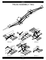
Page 67: ...ETAIL B DETAIL C DETAIL D DETAIL E DETAIL F A C B D F E C19 PARTS 1300060439 09 00 TRUSS ASSEMBLY T852 2 1 4 3 6 5 7 6 9 4 2 6 11 12 13 11 13 15 12 14 1 1 1 16 2 9 10 15 11 14 13 12 13 12 10 11 15 10 2 16 8 8 10 ...

Page 68: ...008 6 Flange Lock Nut 5 8 11 Gr 5 2 13073100010 7 Mount Cable Truss Flange RH T852 62 2 1300011880 00 8 Mount Cable Truss Flange LH T852 62 2 1300011879 00 9 Cable Truss Top 5 16 x 30 2 1300011017 00 10 Truss Upright T852 62 T1052 62 4 1300010163 00 11 NUT HEX FLANGED Steel Mild 3 8 16 UNC 12 13073100006 12 Carriage Bolt 3 8 x 1 16 Gr 5 12 13070906016 13 Cross Truss Support T852 62 T1052 2 1300010...

Page 69: ...L A DETAIL B DETAIL C DETAIL D DETAIL E DETAIL F A B C D E F C21 PARTS 1300060439 10 00 TRUSS ASSEMBLY T862 2 1 3 4 5 6 7 6 9 3 2 10 8 12 13 11 14 1 11 2 12 13 1 8 9 15 2 1 10 2 11 14 12 13 12 11 13 2 15 10 ...

Page 70: ...5 8 13072500008 6 Flange Lock Nut 5 8 11 Gr 5 2 13073100010 7 Mount Cable Truss Flange RH T852 62 2 1300011880 00 8 Mount Cable Truss Flange LH T852 62 2 1300011879 00 9 Cable Truss Top 3 8 x 42 T862 T1062 2 1300011707 00 10 Truss Upright T852 62 T1052 62 6 1300010163 00 11 NUT HEX FLANGED Steel Mild 3 8 16 UNC 18 13073100006 12 Carriage Bolt 3 8 x 1 16 Gr 5 18 13070906016 13 Cross Truss Support T...

Page 71: ...C23 PARTS 1300060439 74 00 WINCH CABLE ASSEMBLY T8 1 2 ...

Page 72: ...Cable Frame Lift 1 4 x 55 T852 Cable Frame Lift 5 16 x 63 T862 1 1300010956 00 1300011943 00 1300011016 00 1300011708 00 1 1 4 Galv Cable Clamp 2 13000001060 00 2 C24 PARTS 1300060439 74 00 WINCH CABLE ASSEMBLY T8 REF PART QUANTITY DESCRIPTION HARVEST by MERIDIAN T8 ...

Page 73: ...C25 PARTS 1300060439 06 00 DISCHARGE HEAD T832 T836 T842 1 2 3 4 5 6 7 8 9 10 11 12 13 14 15 8 16 17 20 21 22 23 24 19 18 10 ...

Page 74: ...UNC 2 13073100006 12 Bearing c w 2 Bolt Housing 1 Bore 1 1300030563 00 13 Gasket Bearing T8 T1032 36 42 52 1 1300010965 00 14 Flange Lock Bolt 3 8 x1 1 2 16 Gr 5 2 13071206024 15 Pin Roll 7 32 x 1 1 2 1 1300011401 00 16 Spacer Sprocket Bearing Head End T1032 36 42 52 4 1300010306A 00 17 Sprocket 60B20 1 1 4 Hardened c w 2 5 16 S S 1 4 K W 1 13000002033 00 18 Washer Spacer Sprockets H13XT T8 13 T10...

Page 75: ...C27 PARTS 1300060439 07 00 DISCHARGE HEAD T852 1 2 3 4 5 6 7 4 8 9 10 11 12 13 14 15 6 16 15 17 18 19 20 21 22 ...

Page 76: ...lange Lock Bolt 3 8 x1 1 2 16 Gr 5 2 13071206024 11 Nylon Locknut 1 4 20 Gr 5 8 13072900004 12 Fitting Hyd 6MP Plug 1 1300010339 00 13 Cotter Pin 3 16 x 1 3 4 1 13073706056 14 Spacer 1 1 4 Bore Head End T1062 T13 3 1300011608 00 15 Sprocket 60B20 1 1 4 Hardened c w 2 5 16 S S 1 4 K W 1 13000002033 00 16 Washer Spacer Sprockets H13XT T8 13 T1062 1 1300060219 00 17 Stover Locknut 1 2 13 Type B Gr 5 ...

Page 77: ...C29 PARTS 1300060439 08 00 DISCHARGE HEAD T862 1 2 3 4 5 6 7 4 8 9 10 11 12 14 15 6 16 15 17 18 19 20 21 22 13 ...

Page 78: ...lange Lock Bolt 3 8 x1 1 2 16 Gr 5 2 13071206024 11 Nylon Locknut 1 4 20 Gr 5 8 13072900004 12 Fitting Hyd 6MP Plug 1 1300010339 00 13 Cotter Pin 3 16 x 1 3 4 1 13073706056 14 Spacer 1 1 4 Bore Head End T1062 T13 3 1300011608 00 15 Sprocket 60B20 1 1 4 Hardened c w 2 5 16 S S 1 4 K W 1 13000002033 00 16 Washer Spacer Sprockets H13XT T8 13 T1062 1 1300060219 00 17 Stover Locknut 1 2 13 Type B Gr 5 ...

Page 79: ...C31 PARTS 1300060439 75 00 FORK T8 1 2 8 3 9 10 10 11 5 7 6 4 ...

Page 80: ...13073000008 5 Stub Bearing Fork T8 10 1 1300010282 00 6 Hex Cap Screw 1 2 x 2 1 2 13 Gr 5 1 13070208040 7 Hair Pin 1 8 x 1 15 16 2 13073902031 8 Flange Lock Bolt 3 8 x1 1 4 16 Gr 5 4 13071206020 9 NUT HEX FLANGED Steel Mild 3 8 16 UNC 8 13073100006 10 BOLT HEX FLANGED Steel Mild 3 8 16 UNC X 1 4 13071206016 11 C32 PARTS 1300060439 75 00 FORK T8 REF PART QUANTITY DESCRIPTION HARVEST by MERIDIAN T8 ...

Page 81: ...C33 PARTS 1300060439 76 00 HOPPER T8 9 8 10 1 2 3 7 6 5 4 14 15 8 13 17 12 18 19 20 11 12 16 23 24 22 25 23 24 22 21 26 28 27 30 31 30 26 29 27 32 33 2 34 35 36 37 38 39 ...

Page 82: ...onnection Hopper T8 1 1300030911 00 18 Cotter Pin 1 8 x 1 1 2 1 13073704048 19 Connection Band Clamp Mount Hopper T8 1 1300030912 00 20 Flight Hopper Flex T8 1 1300030906 00 21 Key 1 4 x 1 4 x 1 1 2 2 13000006743 00 22 Flange Lock Nut 5 16 18 Gr 5 2 13073100005 23 Socket S Screw 5 16 x 1 1 4 18 2 13074205020 24 Flight Transition Hopper T8 1 1300030907 00 25 Flange Lock Bolt 1 4 X 3 4 20 Gr 5 35 13...

Page 83: ... 4 5 1 12 13 14 15 16 9 8 7 6 2 3 11 10 9 18 17 19 20 21 23 22 24 25 26 27 NOTE Items 1 4 and 6 11 does not supply with the option kit they are part of parent hardware box Qty of Item 4 varies for T832 T836 T842 and T852 Items 12 15 are only for T836 T842 and T852 ...

Page 84: ...13070905016 12 Bearing 1 D Roller w Lock Collar T8 10 13 1 1300010670 00 13 Flangette 2 Bolt 1 Bearing 2 1300010656 00 14 Flange Lock Nut 5 16 18 Gr 5 2 13073100005 15 T832 Drive Shaft Intake PTO T832 T1032 T836 Drive Shaft Hopper Extended Gearbox T836 T842 Drive Shaft Intake PTO T842 T1042 T852 Drive Shaft Intake PTO T1052 T1342 1 1300011777 00 1300011857 00 1300011856 00 1300011855 00 16 Spring ...

Page 85: ...060439 78 00 PTO DRIVE OPTION T862 3 2 4 1 4 5 4 5 15 14 13 16 12 10 11 8 9 7 6 2 3 17 18 19 20 21 10 23 22 24 25 26 27 NOTE Items 1 4 and 6 11 does not supply with the option kit they are part of parent hardware box ...

Page 86: ... 5 16 x 1 18 Gr 5 6 13070905016 13 Flangette 2 Bolt 1 Bearing 6 1300010656 00 14 Bearing 1 D Roller w Lock Collar T8 10 13 3 1300010670 00 15 Flange Lock Nut 5 16 18 Gr 5 6 13073100005 16 Spring Lock Washer 5 16 4 13073400005 17 Hex Cap Screw 5 16 x 1 2 18 Gr 5 4 13070205008 18 Housing Guard PTO T8 10 13 1 1300010923 00 19 Flange Lock Nut 1 4 20 Gr 5 6 13073100004 20 PTO TR35ND P 14 x 1 3 8 6 Spli...

Page 87: ...25 does not supply with the option kit they are part of parent hardware box Item 20 only for T836 Items 22 and 26 are only for T836 and T862 5 6 4 3 2 1 8 10 8 11 12 13 14 10 7 8 9 10 21 18 19 20 20 22 24 23 15 16 17 18 19 25 28 27 26 8 10 24 30 31 32 33 34 35 24 38 39 37 36 29 ...

Page 88: ...box Right Angle H13XT T8 10 13 1 1300030176 00 17 Spring Lock Washer 1 2 8 13073400008 18 Hex Cap Screw 1 2 x 1 13 Gr 5 8 13070208016 19 Screw Self Tapping 12X3 4 T832 42 52 62 2 T836 4 1300010304 00 20 Cover Chain Coupler T8 10 13 1 1300012529 00 21 Guard Drive Shaft 60 T862 T1036 62 1 1300011435 00 22 Sprocket c w Hub T8 T1032 36 42 1 1300031685 00 23 NUT HEX FLANGED Steel Mild 3 8 16 UNC 11 130...

Page 89: ...or mixing fertilizer canola etc or used in excess of the built specifications e Goods used in areas exposed to corrosive or aggresive conditions including but not limited to salt water from either inside or outside the Goods f Failures or defects arising out of damage during shipment or during storage g Materials replaced or repaired under this warranty except to the extent of the remainder of the...

Page 90: ...claim against Harvest by Meridian relating to any such warranty d Subject to Harvest by Meridian s obligations contained in paragraphs 1 and 2 herein none of Harvest by Meridian its officers directors servants or agents shall be liable or responsible for any loss or damage including strict liability and liability for loss or damage due to items which the manufacturing processes are designed to ide...

Page 91: ...588 PH 712 732 1780 TF 800 437 2334 FX 712 732 1028 Lethbridge Office 3125 24 Ave N Lethbridge AB T1H 5G2 PH 403 320 7070 TF 800 661 1436 FX 403 320 7579 Regina Office PO Box 1996 Regina SK S4P 3E1 PH 306 545 4044 TF 800 667 5904 FX 306 545 4216 Camrose Office 4232 38 St Camrose AB T4V 4B2 PH 780 672 4516 TF 800 830 2467 FX 780 672 4759 MERIDIAN MANUFACTURING INC With over 65 years of experience M...

Reviews: