Lepus 5/13 QuickStickNabe F-ENG
14
STOP
Régler la direction
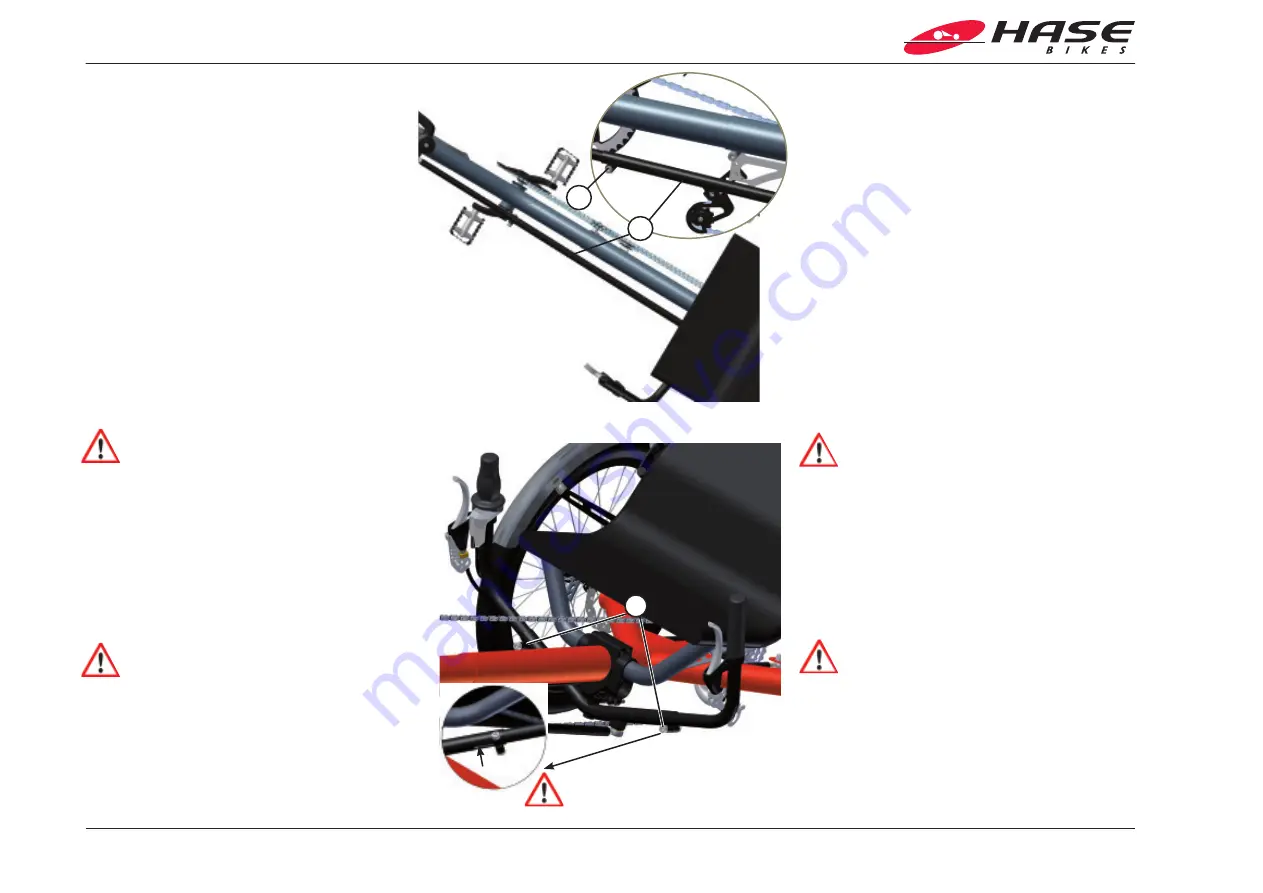
Les mouvements du guidon sont transmis à la roue avant au
moyen d’une biellette de direction (1). Cette dernière est
composée de deux tubes coulissants, insérés l’un dans l’autre,
fixés à l’aide d’un œil de serrage. Après modifications de la
longueur du Lepus, le guidon doit être de nouveau aligné.
1. Desserrez la vis à six pans creux (2) au niveau de la bielle
de direction (côté gauche du Lepus) à l’aide d’une clé mâle
adaptée de 5 mm. Placez la roue avant sur «Direct» et
maintenez-la dans cette position.
2. Orientez le guidon dans un angle droit par rapport au
cadre principal.
3. Serrez la vis à six pans creux (2) au niveau de la bielle de
direction à l’aide d’une clé mâle adaptée de 5 mm.
4. Contrôlez la liberté de mouvement de la direction en
déplaçant le guidon vers la gauche et vers la droite jusqu’à
la butée.
Attention !
Les limitations de la liberté de mouvement peuvent
entraîner des accidents avec des blessures.
Régler la largeur et l’inclinaison du guidon
Vous pouvez adapter la largeur et l’inclinaison du guidon à la
largeur de vos épaules et à la longueur de vos bras.
1. Desserrez les vis (1) de part et d’autre du guidon à l’aide
d’une de Allen 6 mm.
2. Retirez les extrémités du guidon pour élargir le guidon ou
insérez les extrémités du guidon pour le rétrécir.
Attention !
Les poignées du guidon ne doivent pas être sorties au
point qu‘on en voie l‘extrémité dans la fente se trouvant
dans la pièce centrale du guidon. Risque d’accident ! A
l’effort, la pièce centrale risque de se rompre.
Les poignées ne doivent pas être sorties au point de
buter contre Les roues et/ou les garde-boues. Risque
d’accident ! En braquage maximal, la direction pourrait
se bloquer.
1
2
Adjusting the steering
The movements of the handlebars are conveyed to the front
wheel by means of a steering rod (1). The steering rod con-
sists of two tubes, the smaller of which fits inside of the larger
and can be moved to adjust the length. Their position is fixed
by means of a clamping bolt. The steering rod must be read-
justed if the length of the Lepus has been changed.
1. Loosen the Allen bolt (2) on the steering rod (left side of
the Lepus) with a 5mm Allen key. Position the front wheel
so that it is pointing forward and hold it in this position.
2. Position the handlebar so that it is perpendicular to the
main frame.
3. Tighten the Allen bolt (2) on the steering rod with a 5mm
Allen key.
4. Check that the handlebar has full freedom of movement
by moving it as far as it will go to the left and to the right.
Caution!
Any restrictions in handlebar movement could lead to
accidents with possible injuries.
Adjusting the handlebar width / angle
You can adjust the width and angle of the handlebar to fit
your shoulder width and arm length.
1. Loosen the bolts (1) on each side of the handlebar using a
6mm Allen key.
2. Pull out the handlebar grips in order to increase the
width, or push the grips further in to decrease the width.
Caution!
The ends of the grips should not be visible through the
slots in the center section of the handlebar. This means
they have been pulled out past their minimum insertion
length. Major risk of accident! If too much pressure is
placed on the grips, the center section could break.
Make sure that the handlebar grips are not pulled out so
far that they bump against the wheels or fenders. Major
risk of accident! The steering could lock in the handle-
bar’s maximum left or right position.
1
Adapter le Lepus à votre taille
Adjusting your Lepus
Summary of Contents for LEPUS COMFORT
Page 1: ...Mode d emploi Lepus 5 13ce F ENG LEPUS User s Manual ENG F LEPUS CUSTOM LEPUS COMFORT ...
Page 2: ......
Page 34: ......


