Air Driven Liquid Pump 4B Series • OM-16F
3
E. Check for visible damage to the sleeve or the (5) static o-rings (scores, scratches, etc.), and
replace as needed. Lubricate the (4) static o-rings on the sleeve O.D. (P/N 568018-2).
F. Push the sleeve back inside. Lightly lubricate and insert 568021-2 o-ring on the end of the sleeve,
using the plug to push it into position.
G. Lightly lubricate and install 568021-2 o-ring on the plug. Push the plug past the snap ring groove
in the casting and into contact with the end of the sleeve.
H. Replace Tru Arc ring.
4.0
Disassembly and Inspection
4.1
Air Drive Section
A. Unscrew muffler.
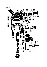
B. Remove the (4) tie bolts and the mounting brackets.
C. Remove the upper valve cap assembly.
D. Remove the air pilot tube (3/8" O.D.).
E. Remove the air flow tube (5/8” O.D.).
F. Pull the 55278 barrel off the air piston. The air piston and plunger assembly may be removed
from the body if required. lnspect plunger for scoring or other damage.
G. lnspect all exposed o-rings. Test the large 56225 o-ring for possible shrinkage by laying it on
a flat surface. When it is wiped free of all grease, you should be able to pick it up with a
grease free air barrel. If you cannot, discard it as undersize.
H. Reassemble the drive according to steps 5.0 C through J.
4.2
Air Pilot Valves
A. Note that the two valves are identical except for the length of the pilot pin. The longer part
number 27375-5 is used in the upper air cap casting that also contains the cycling valve.
B. You can replace either valve easily by removing the access plug and spring. Use 28584 tool,
slanted, to pull out the pilot valve and inspect the molded rubber seats for damage.
C. Valve stem seal o-rings 568006-2. Access is only by disassembling the air drive according to
steps 4.1 A through G under Air Drive Section.
D. To replace either o-ring remove the retainer 5005-31 H and spacer with a small screwdriver
or sharp tool. Discard part number 5005-31 H which is not reusable.
E. To reinstall the above parts, reuse pilot valve stem as a centering tool to make sure that the
legs of the 5005-31H retainer are deflected evenly. Tap in place.
4.3
Inlet Check Valve
Access to service or change high pressure seals is through the inlet check valve assembly. Follow
the procedure below.
A. Disassemble the drive section according to steps 4.1 A through G under Air Drive Section.
Withdraw the piston/plunger assembly from the hydraulic pump body.
B. Remove the inlet check valve, being very careful not to lose any inner parts: o-ring, seat, ball
cage, ring, spring guide and ball.
4.4
Plunger Seal
A. Remove the white plastic spacer.
B. Push a pin or dowel with fairly close fit through the inside end of the hole in the hydraulic
body to push the seal package out the inlet port. (On -100 and -150 model pumps, first
remove the item (47) o-ring).

