background image

Air Driven Gas Booster Compressor, 5-3/4” Drive AG Series • OM-3F 

unswept volume expands to inlet pressure. This reduces the amount of potential fresh gas intake on the 
suction stroke. Volumetric efficiency therefore decreases rapidly with an increase in compression ratio 
until the volumetric efficiency reaches zero when the unexpelled (expanded) gas completely fills the 
cylinder at the end of the intake stroke. A cylinder with a 4% unswept volume will reach zero efficiency at 
a compression ratio of approximately 25:1. 

Production models of Haskel gas boosters are tested in the laboratory. Results of these tests indicate that 
compression ratios of up to 40:1 are possible for some models under ideal conditions. However, for 
satisfactory operation under production conditions in industrial applications, we recommend compression 
ratios (per stage) of about 10:1 or less. Operation at higher ratios may not damage the gas booster but 
because output flow and efficiency will be low, the use should be limited to pressurizing small volumes 
such as pressure gauge testing, etc. 

COOLING 

Effective cooling of the gas pumping section is of paramount importance as service life of piston seals, 
bearings, and static seals are dependent upon proper operating temperatures. Haskel gas boosters use 
the exhaust air from the driving system to cool the gas barrel (and gas intercooler on the two stage 
models). Driving air expands during the work cycle with a significant reduction in temperature. Therefore, 
the exhaust air is a very efficient cooling medium. 

In theory, compression ratios above 3:1 with most gases produce temperatures above the allowable limits 
for the seals. In practice, however, the heat of compression is transferred to the air cooled gas barrel and 
adjacent metal components during the relatively slow speed of the piston on the compression stroke and 
these components will stay within allowable temperature limits. Laboratory tests indicate that maximum 
temperatures occur between compression ratios of 5:1 and 10:1 and have shown that exhaust air cooling 
is adequate even when the booster is running at full speed. 

The gas discharge temperature may run as high as approximately 150°F above ambient temperature. 
Under certain severe operating conditions, it may be necessary to slow down the cycling of the gas 
booster to prevent overheating. It is very difficult to predict exactly when overheating may occur. To test, 
install a thermocouple approximately 1 inch from the discharge port of the gas pumping section. 
Temperatures above 300°F at this point will shorten piston seal life considerably. 

Summary of Contents for 5-3/4" Drive AG Series

Page 1: ...e Funcionamento e Manutenção Air Driven Gas Booster Compressors 5 3 4 Drive AG Series Surpresseurs d Air Pneumatique à Gaz Entraînement 5 3 4 Série AG Luftdruck Gas Booster Druckluftzylinder Kompressoren Schalldämpfer 5 3 4 Antrieb AG Reihe Compressori Generatore a Gas Trasmissione ad Aria Serie Trasmissione AG 5 3 4 Compressores de Gás Tipo Gas Booster com Comando Pneumático Série AG 5 3 4 ...

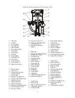
Page 2: ...elter Druckluftkopf Doppelt Wirkend Oder 2 Stufig 3 Druckluftzylinder 4 Verbindungsstange 5 Schalldämpfer 6 Hochdruckzylinder 7 Pumpenausgang 8 Rückschlagventile 9 Pumpeneingang 10 Kühlmantel 11 Abluftleitung 12 Pumpenkolben 13 Lufttaktventil 14 Luftdruckantr Eingangsanschl 15 Obere Untere Kappen 1 Valvola Pilota 2 Pistone Ad Aria 3 Barrel A Trasmissione Ad Aria 4 Collegamento All asta 5 Scarico M...

Page 3: ...nd of this spool valve The control valve pilot valves and drive cylinder are lubricated with Haskel air drive grease part no 50866 at assembly Occasional relube of the easily accessible control valve and pilot valves with this grease may be needed depending on the duty cycle of the installation It is recommended that only o rings and seals of proper compounds and hardness for low friction be used ...

Page 4: ...tatic seals are dependent upon proper operating temperatures Haskel gas boosters use the exhaust air from the driving system to cool the gas barrel and gas intercooler on the two stage models Driving air expands during the work cycle with a significant reduction in temperature Therefore the exhaust air is a very efficient cooling medium In theory compression ratios above 3 1 with most gases produc...

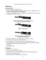
Page 5: ... bumper hook through center of bumper and pull straight out 3 Replace any 568020 o rings or the bumper spacer if damaged worn or swollen 4 Lubricate o rings with light coat of Haskel 50866 lubricant 5 Use lubricant liberally to hold bumper spacer to sleeve with rubber side facing sleeve 6 Push lubricated sleeve and bumper into end cap bore all the way in one quick motion If bumper drops off sleeve...

Page 6: ... immediately rise or fall from zero to pilot air pressure A slow increase in gauge reading indicates leakage past the seat of the pilot valve in the valve end cap A slow decrease in pressure indicates leakage past the seat of the opposite pilot valve Examine and replace as required Check also for external air leaks at plugs 4 If drive takes 1 stroke and stops this is probably due to either pilot v...

Page 7: ...otection de la vanne dans le capuchon de protection opposé d un tube de courant pour diriger le débit d injection d air depuis le capuchon de protection de la vanne jusqu au capuchon de protection opposé et d un tube pilote pour connecter les deux robinets pilotes qui sont en série La vanne de régulation du mécanisme à entraînement fonctionne sans ressorts ou détentes et est cyclée alternativement...

Page 8: ...re limitée à des petits volumes pressurisés comme le test de la jauge de pression etc REFROIDISSEMENT Le refroidissement efficace de la section de pompage à gaz est d une importance prépondérante pour la durée de vie de fonctionnement des joints du piston des supports des joints statiques qui dépendent des bonnes températures de fonctionnement Les surpresseurs à gaz Haskel utilisent l air évacué d...

Page 9: ...rangée de trous du gainage et si nécessaire écarter avec un tournevis Schéma 2 Tirer Schéma 3 Insérer le crochet du pare chocs au centre du pare chocs et tirer Système Pilote 1 Enlever le raccord d étanchéité de l anneau torique hex 2 Enlever le ressort et la tige de manoeuvre pilote 27375 schéma 4 3 Inspecter la tige de manœuvre pilote et installer les matériaux étrangers Remplacer la tige si le ...

Page 10: ...s bouchons 4 Si le mécanisme à entraînement effectue 1 course et s arrête ceci est probablement dû à la tige de manoeuvre pilote étant trop courte Voir le schéma de montage pour une description de la procédure pour déterminer la bonne longueur de la tige de manoeuvre Pour le démontage et la réparation de la section du mécanisme à entraînement d air et du piston à air 1 Enlever les quatre boulons d...

Page 11: ...n Reihe geschalteten Steuerventile Das Antriebssteuerventil arbeitet ohne Federn und Sperren und wird über das Steuerventil getaktet das abwechselnd die große Fläche am inneren Ende dieses Spulventils mit Druck versorgt und entlüftet Das Regelventil die Steuerventile und der Antriebszylinder werden mit Haskel Schmiermittel Teile Nr 28442 auf der Baugruppe geschmiert Gelegentlich müssen das einfach...

Page 12: ...eiten mit der Abluft aus dem Antriebssystem um den Gaszylinder zu kühlen und die Gaszwischenkühlung auf den 2 Phasen Modellen Die Antriebsluft weitet sich während des Arbeitstakts aus und die Temperatur fällt stark ab Daher ist die Abluft ein überaus geeignetes Kühlmedium In der Theorie erzeugen Verdichtungsverhältnisse über 3 1 bei den meisten Gasen Temperaturen die die Grenzwerte für die Dichtun...

Page 13: ...ade heraus Steuersystem 1 Nehmen Sie den mit dem Sechskantstopfen abgedichteten O Ring heraus 2 Bauen Sie die Federn und die 27375 Pilotsplinte aus Abb 4 3 Prüfen Sie den Schaft des Steuerventils und den Sitz auf Fremdmaterial Tauschen Sie das Ventil aus wenn der Schaft verbogen oder zerkratzt ist 4 Ersetzen Sie den Schaft falls die Dichtung beschädigt sein sollte 5 Tragen Sie Schmiermittel 28442 ...

Page 14: ...s Ventil und tauschen Sie es ggfs aus Prüfen Sie die Stopfen ebenfalls auf Luftaustritt 4 Wenn der Antrieb 1 Mal taktet und stoppt ist der Schaft des Steuerventils eventuell zu kurz Ziehen Sie die Montagezeichnung heran um die korrekte Schaftlänge zu ermitteln Ausbau und Reparatur des Luftdruckabschnitts und des Druckluftkolbens 1 Entfernen Sie die vier Spannschrauben 2 Entfernen Sie den Luftzylin...

Page 15: ...a valvola al terminale della calotta opposto e un tubo pilota per collegare le due valvole pilota che sono in serie La valvola di controllo di trasmissione opera senza molle o fermi ed è operata in cicli per mezzo delle valvole pilota pressurizzando alternativamente e ventilando la zona ampia sulla fine interna di tale valvola a tamburo la valvola di controllo le valvole pilota e il clindro di tra...

Page 16: ...e il generatore di gas ma siccome il flusso di uscita e l efficienza saranno bassi l utilizzo deve essere limitato alla pressurizzazione di volumi di ridotte dimensioni come verifica di misura della pressione ecc RAFFREDDAMENTO Il raffreddamento effettivo della sezione del gas pompato è di somma importanza per la durata dei sigilli dei pistoni della direzione e i sigilli statici dipendono dalla gi...

Page 17: ...utti gli anelli ad o 568020 o il basamento distanziatore se danneggiato usurato o rigonfio 4 Lubrificare gli anelli as O con sigillante leggero lubrificante Haskel 28442 anelli ad o con leggera patina di lubrificante 28442 5 Usare lubrificante liberamente per isgrassare il manicotto con la gomma di fronte al manicotti 6 Spingere il manicotti lubrificato al terminale del foro del coperchio con una ...

Page 18: ...pilota Un leggero aumento nella lettura del calibre indica perdita precedente della sede della valvola pilota nel coperchio terminale della valvola Una lenta diminuzione della pressione indica perdita precedente nella sede della valvola pilota opposta Esaminare e sostituire come richiesto Controllare anche le perdite d aria esterne negli scarichi 4 Se la trasmissione viene colpita e si arresta il ...

Page 19: ...bo de escoamento para conduzir o fluxo de ar da tampa terminal da válvula até a tampa oposta e um tubo piloto para para conectar as duas válvulas piloto instaladas em série A válvula de controle pneumática funciona sem molas ou limitadores e é acionada ciclicamente pelas válvulas piloto que alternadamente pressurizam e ventilam a ampla zona que se encontra no extremo interno da válvula carretel A ...

Page 20: ...is e selos estáticos depende de se opere a temperaturas adequadas Os compressores booster de gás Haskel utilizam o ar de escape do sistema propulsor para refrigerar o cilindro de gás e o intercooler de gás nos modelos de dois estágios O ar propulsor se expande durante o ciclo de operação com uma conseqüente grande redução da temperatura Por isso o ar de escape torna se um refrigerante muito eficaz...

Page 21: ...mova o lubrifique novamente e repita o processo 7 Instale o carretel 8 Recoloque a conexão do tubo de escape Sistema Piloto 1 Remova o bujão sextavado vedado com anel o ring 2 Remova a mola e a haste da válvula piloto PN 27375 Figura 4 3 Inspecione a haste e a sede para ver se há material estranho Substitua a haste caso o cabo esteja torto ou riscado 4 Substitua a haste caso a sede moldada esteja ...

Page 22: ...á vazamentos externos nos bujões 4 Se a máquina executa um só tempo e pára é provavelmente porque a haste de alguma das válvulas piloto é muito curta Consulte o procedimento de determinação do comprimento correto da haste no desenho de conjunto Para Desmontagem e Reparo da Seção do Comando Pneumático e do Pistão 1 Remova os quatro tirantes 2 Remova o cilindro pneumático e os anéis de vedação o rin...

Page 23: ...istance for lifting e Safety labels on the machines and meanings are as follows General Danger Read Operator s Manual f In an emergency turn off the air supply g Warning If the pump s were not approved to ATEX it must NOT be used in a potentially explosive atmosphere h Pressure relief devices must be installed as close as practical to the system i Before maintenance liquid section s should be purg...

Page 24: ...s Any modification to any Haskel product which you have made or may make in the future has been and will be at your sole risk and responsibility and without Haskel s approval or consent Haskel disclaims any and all liability obligation or responsibility for the modified product and for any claims demands or causes of action for damage or personal injuries resulting from the modification and or use...

Reviews: