Air Driven Air Amplifiers, AAD-2 & AAD-2-C • OM-9J
3
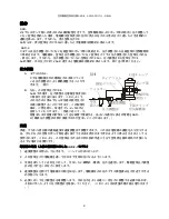
Pressure Control
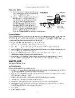
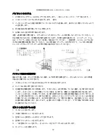
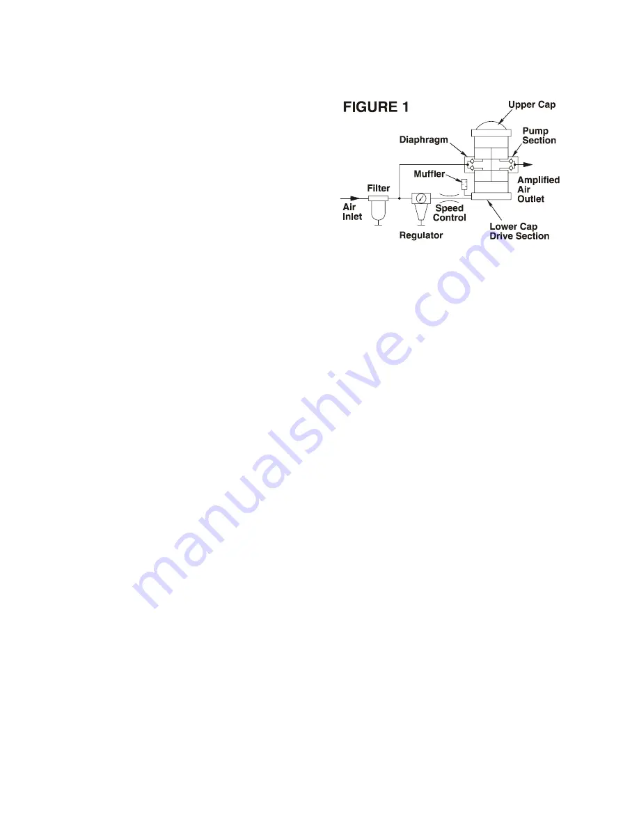
A. On model AAD-2-C, maximum amplifier outlet
air pressure can be roughly controlled with the
regulator on the drive, (Figure 1).
B. However, if the air inlet pressure is 125 psi or
less, the regulator can be moved to the
amplified air outlet port. Here it will provide
precise final pressure regulation at any
selected pressure up to 2 times air inlet
pressure. This piping arrangement can be
specified at time of order by requesting
modification 53375. (It may also be desirable
to tee in a small or large air storage tank or
install a length of pipe between the AAD-2
outlet and the final regulator, depending on the application.)
Pumping Speed
The pumping speed or cycling speed of the amplifier may be controlled by the speed control valve. This
valve is also an on/off valve to stop the amplifier yet allow inlet air to flow straight through the pump
section to outlet. This is useful in installations where air inlet pressure by itself is sometimes sufficient for
the application downstream without help from the air amplifier.
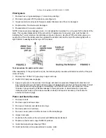
Starting the Amplifier - (Model AAD-2-C per schematic above)
1. Speed control valve should be closed. (Handle at 90° to valve.)
2. Allow inlet air to equalize pressure through the amplifier and to fill the entire outlet system.
3. Select the approximate (maximum) pressure desired to be added to the equalized pressure. Set this
amount on the gauge of the drive air regulator.
4. Open speed control valve and allow amplifier to pressurize outlet system. It should stall at
approximately equalized pressure plus regulated pressure.
5. Readjust regulator if necessary. If more precise, constant control of output pressure is desired,
relocate regulator per suggestion B above. (This will also increase output flow capacity.)
MAINTENANCE
(Ref. dwgs. 27360 and 27369)
Air Valve Section
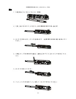
Remove spool or sleeve in the following manner:
1. Remove air exhaust muffler and fitting located in the lower end cap. Pull out spool; inspect 568017 o-
rings.
Relube; reinstall; retest before further disassembly.
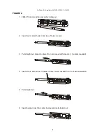
2. If necessary remove sleeve and bumper (rubber faced spacer at inside end of sleeve) with tool P/N
28584 as shown in drawings 4 thru 6.
3. Replace any 568020 o-rings or the bumper - spacer if damaged, worn, or swollen.
4. Lubricate o-rings with light coat of Haskel 50866 lubricant.
5. Use lubricant liberally to hold bumper - spacer to sleeve with rubber side facing sleeve.
6. Push lubricated sleeve and bumper into end cap bore, all the way in one quick motion. (If bumper
drops off sleeve too soon, remove, regrease and repeat.)
7. Install
spool.
8. Replace fitting and muffler.

