7 |
P a g e
2.0 INSTALLATION
2.4 Electrical Power (continued)
Correcting Motor rotation in systems
using 3-Phase power
A licensed electrician should interchange
any two wires of the three-phase power
source at the disconnect switch to correct
improper pump rotation or improper phase
displayed by the phase monitor.
Phase Monitor Factory settings
Voltage line-line
At nameplate
voltage
Trip Delay
At 10 seconds
Unbalance
At 5%
Restart Delay
At 180 seconds
Under voltage Trip
At 90%
1)
Apply power to chiller.
2)
LED on phase monitor will blink
green for 180 seconds.
3)
LED will be green and on solid
indicating all is OK.
4)
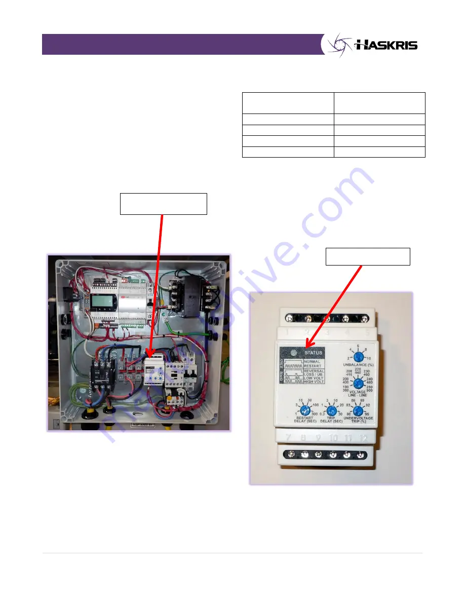
See photo below for error codes.
Phase Monitor
STATUS CODES
Summary of Contents for OPC 12
Page 7: ...4 P a g e 2 0 INSTALLATION 2 2 System Location Continued ...
Page 8: ...5 P a g e 2 0 INSTALLATION ...
Page 15: ...12 P a g e 2 0 INSTALLATION ...
Page 26: ...23 P a g e 6 0 WARRANTY 5 0 MAINTENANCE ...
Page 27: ...24 P a g e 6 0 WARRANTY 5 0 MAINTENANCE ...
Page 28: ...25 P a g e 6 0 WARRANTY 5 0 MAINTENANCE ...
Page 29: ...26 P a g e 6 0 WARRANTY 5 0 MAINTENANCE ...
Page 30: ...27 P a g e 6 0 WARRANTY 5 0 MAINTENANCE ...
Page 32: ...29 P a g e 6 0 WARRANTY 5 0 MAINTENANCE ...
Page 33: ...30 P a g e 6 0 WARRANTY 5 0 MAINTENANCE 6 1 Standard Product Warranty 6 0 WARRANTY ...
Page 35: ...32 P a g e 6 0 WARRANTY 7 0 ELECTRICAL AND PIPING DIAGRAMS ...
Page 36: ...33 P a g e 6 0 WARRANTY 7 0 ELECTRICAL AND PIPING DIAGRAMS ...


