22
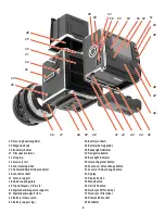
Flash/strobe with film
14, 15
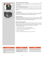
Any flash/strobe unit can be connected to the 503 CW / 503 CWD via the PC flash/strobe
terminal on the lens for manually controlled flash exposure with flash sync speeds are up
to 1/500s.
Automatic flash control, or dedicated flash, is provided by the camera’s built-in flash sensor
and electronics (TTL/OTF) that measure the light reflected from the central portion of the
film; a circle with a diameter of 40 mm.
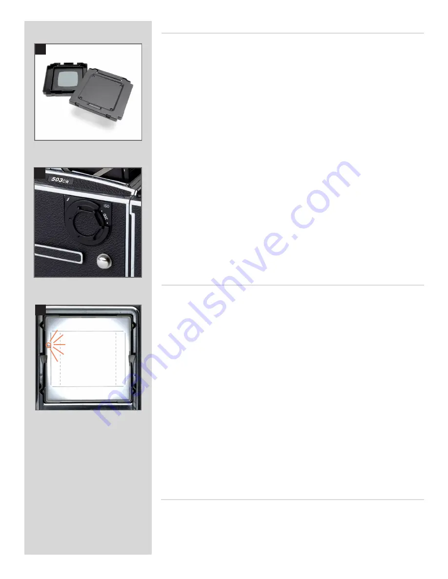
The metering system is connected to a selector for setting film speed. When an SCA 300
compatible flash/strobe unit is connected through an SCA390 flash/strobe adaptor, the
system controls the flash/strobe unit and cuts off the flash when the exposure is correct.
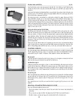
Under the left hand edge of the focusing screen an indicator light shows when the flash is
ready to be operated and also confirms if the flash output was sufficient to give a correct
exposure. The flash/strobe unit powers the camera’s electronics and also the flash/strobe
adaptor, when that is used.
Setting the film speed for TTL/OTF flash
The film speed is set via the ISO selector. This is marked in ISO/ASA settings from 64 − 4000.
Note that certain films require compensation due to differences in reflective properties of
various emulsions. In these instances, the compensation can be made by changing the film
speed selector setting. The amount of compensation has to be determined by experiment.
Alternatively you can replace the magazine with the Rear cover MultiControl for a few test
exposures. The grey surface acts as an 18% grey card to provide a well-balanced starting
point for exposures.
Please refer to your flash/strobe unit’s operating instructions for more information about
other functions when using an automatic flash light-metering that conforms to System SCA
flash/strobe photography with flash sensors, or with non−automatic flash/strobe units.
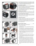
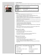
Attaching a Hasselblad flash adaptor SCA 390
For use with hand-held flash/strobe units.
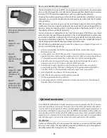
• The 6-pole contact from the spiral cord is connected to the camera’s dedicated flash
connector.
• The sync cord is connected from the adaptor to the PC flash terminal of the lens.
• The flash/strobe unit connecting cord is attached to the flash/strobe unit.
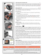
Viewfinder indicator
16
Flash/strobe operation and flash battery–check are indicated by a red light, located under
the left edge of the focusing screen. It is operative only when a dedicated flash/strobe is
connected to the TTL socket. It indicates three separate states as described below.
No result signal
Absence of the flashing confirmation signal after exposure indicates that the flash emitted
was not sufficient for correct exposure. The aperture must then be opened more or the
flash distance to the subject reduced. Changing to a faster ISO setting on the CFV is also
a possibility.
See appropriate manuals for connection details regarding the various units and
adapters.
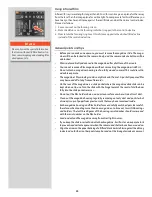
Confirmation signal
A flashing red light occurring for just over a second immediately after exposure confirms
that the light output was sufficient for a proper exposure. It then remains dark until the
flash/strobe unit has recharged. The steady red light will then reappear indicating opera-
tive status again. The time of reappearance however may vary according to the condition
of the batteries.
Ready signal
A steady red light indicates that the flash/strobe unit is charged and ready to be fired.
Absence of any signal indicates the need for fresh batteries.
14
15
16
Summary of Contents for CFV
Page 1: ...User Manual 503CW 503CWD CFV CFVII CFV 39 CFV 50 Version 10 ...
Page 2: ...2 Welcome to Hasselblad 503CW 503CWD CFV ...
Page 6: ...6 1 General Information Photo JoaoCarlos HasselbladMasters ...
Page 28: ...28 1 Overview Photo ClaudioNapolitan HasselbladMasters ...
Page 42: ...42 2 Getting Started Photo MarkHolthusen HasselbladMasters ...
Page 51: ...51 3 Previews Photo MarkZibert HasselbladMasters ...
Page 55: ...55 4 Batches Browsing Photo BangPeng HasselbladMasters ...
Page 61: ...61 5 IAA Instant Approval Architecture Photo LyleOwerko HasselbladMasters ...
Page 66: ...66 6 Delete Format Copy Photo JoaoCarlos HasselbladMasters ...
Page 72: ...72 7 Settings Photo NinaBerman HasselbladMasters ...
Page 73: ...73 Navigating the USER INTERFACE settings ...
Page 85: ...85 8 Cleaning Photo DirkRees HasselbladMasters ...
Page 87: ...87 9 Appendix Photo MarkHolthusen HasselbladMasters ...

