

English
Form No. GR5ALM-0217
15
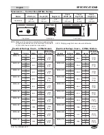
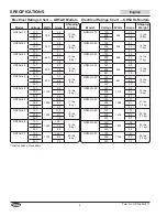
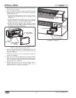
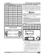
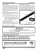
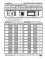
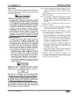
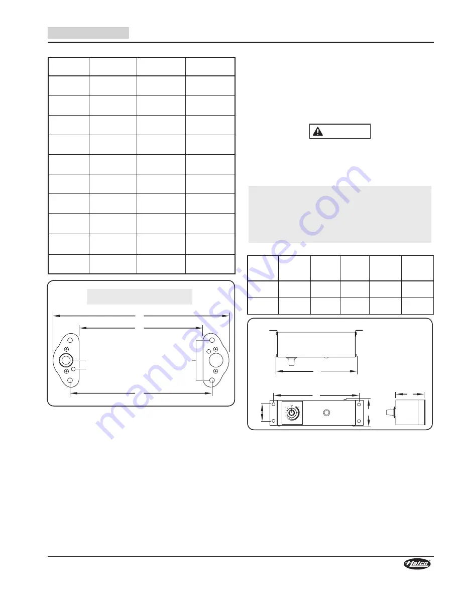
Stand Mounting Measurements
Model
Outside
Flange (A)
Inside
Flange (B)
Mounting
Holes (C)
GR5A-18
GR5AL-18
17-7/16
″
(443 mm)
14-3/16
″
(360 mm)
15-5/16
″
(389 mm)
GR5A-24
GR5AL-24
23-7/16
″
(595 mm)
20-3/16
″
(512 mm)
21-5/16
″
(541 mm)
GR5A-30
GR5AL-30
29-7/16
″
(747 mm)
26-3/16
″
(665 mm)
27-5/16
″
(694 mm)
GR5A-36
GR5AL-36
35-7/16
″
(900 mm)
32-3/16
″
(817 mm)
33-5/16
″
(846 mm)
GR5A-42
GR5AL-42
41-7/16
″
(1052 mm)
38-3/16
″
(970 mm)
39-5/16
″
(999 mm)
GR5A-48
GR5AL-48
47-7/16
″
(1205 mm)
44-3/16
″
(1122 mm)
45-5/16
″
(1151 mm)
GR5A-54
GR5AL-54
53-7/16
″
(1357 mm)
50-3/16
″
(1274 mm)
51-5/16
″
(1303 mm)
GR5A-60
GR5AL-60
59-7/16
″
(1509 mm)
56-3/16
″
(1427 mm)
57-5/16
″
(1456 mm)
GR5A-66
GR5AL-66
65-7/16
″
(1662 mm)
62-3/16
″
(1579 mm)
63-5/16
″
(1608 mm)
GR5A-72
GR5AL-72
71-7/16
″
(1814 mm)
68-3/16
″
(1732 mm)
69-5/16
″
(1761 mm)
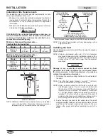
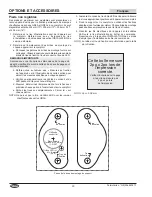
A
C
B
LED Wire Hole
Conduit Hole
Mounting Holes
(2-1/2″ [64 mm]
on center)
Top view of mounting flanges.
Stands removed for clarity.
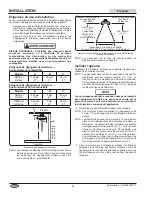
OPTIONS AND ACCESSORIES
Remote Control Boxes — RMB Series
RMB Series remote control boxes are available in various
configurations for use with strip heaters. Remote control boxes
locate controls away from the heat of the unit, increasing the life
span of the controls. All models are built in accordance with UL
standards with switches, indicator lights, and wiring. Consult the
factory for type and location of RMB Series controls for enclosure.
NOTE: RMB Series remote control boxes require one remote
control box per strip heater.
WARNING
ELECTRIC SHOCK HAZARD: Turn OFF power switch,
disconnect unit from power source, and allow unit to
cool before performing any cleaning, adjustments, or
maintenance.
1. Determine the area to mount the RMB box.
IMPORTANT NOTE:
Remote-mounted control boxes and control switches must
be installed in a cool, dry location as far away from any heat
zone as possible. Do not mount control boxes or switches
directly on, under, or above unit. Do not mount control boxes
or switches in direct contact with any heated surface or near
any steam generating equipment.
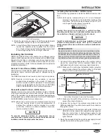
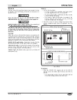
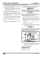
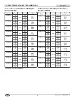
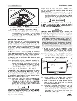
Dimensions
Model
Width
(A)
Depth
(B)
Height
(C)
Screw
WIdth
(D)
Screw
Height
(E)
RMB-3
Series
5-15/16″
(150 mm)
3″
(76 mm)
2-5/8″
(67 mm)
6-5/16″
(161 mm)
1-5/8″
(41 mm)
RMB-7
Series
9-3/8″
(239 mm)
3″
(76 mm)
2-5/8″
(67 mm)
9-13/16″
(249 mm
1-5/8″
(41 mm)
D
E
C
B
A
Side View
Top View
Front View
Remote Control Box Dimensions
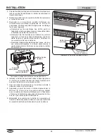
2. Secure the RMB to the mounting surface using appropriate
screws or fasteners.
• Use the mounting flange on each end of the RMB.
NOTE: Sizing of the power supply wire leads and upstream
overcurrent protection must conform with National Electric
Code (NEC) requirements as well as all local codes.
3. Remove the wiring access cover on bottom of the control
enclosure by removing screws and sliding cover off.
4. Identify and remove the appropriate knockouts from the
control enclosure for the electrical connections.
5. Attach conduit connectors to the knockouts in the control
enclosure.
continued...


