INSTALLATION
8
Form No. GRHWm-0111
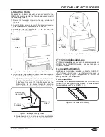
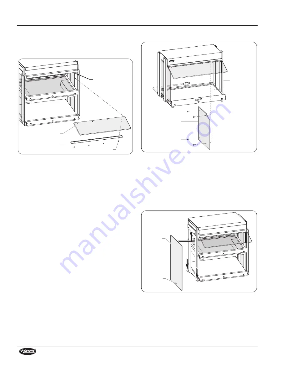
GRHW-1SGD and GRHW-1SGDS Models
1. align the four holes in the sneeze guard and support trim with
the four studs located underneath the front top of the unit.
2. Secure the sneeze guard and support trim to the studs with the
four supplied cap nuts. Do not over-tighten the cap nuts.
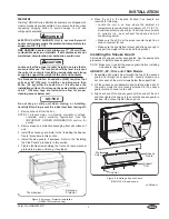
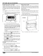
Figure 10. Installing a Sneeze Guard
(GRHW-1SGDS model shown)
Installing the Side Panels
Some models are shipped with side panels. Use the appropriate
procedure to install side panels on a unit.
GRHW-1P, -2P, -1SG, and -1SGS Models
The above models can be equipped with polycarbonate side
panels. To install a polycarbonate side panel:
NOTE: Make sure to install the sneeze guard before installing
side panels, if equipped.
1. align the four holes in the side panel with the corresponding
holes in the two support posts.
• make sure the slanted edge of the side panel is aligned
with the sneeze guard.
Sneeze Guard
Stud
Support Trim
Cap Nut
2. Secure the side panel to the support posts using the four
supplied screws. Do not over-tighten the screws.
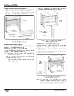
Figure 11. Polycarbonate Side Panel Installation
(GRHW-1SG model shown)
GRHW-1SGD and GRHW-1SGDS Models
all GRHW-1SGD and GRHW-1SGDS models are equipped
with glass side panels. To install a glass side panel:
1. Slide the top of the glass side panel up into the upper
channel.
2. align the bottom of the glass side panel with the lower
channels, then lower into position.
Figure 12. Glass Side Panel Installation
(GRHW-1SGDS model shown)
NOTE: Side glass panels have a special “Low E” coating
applied to one side to help reduce heat loss through the
glass. The “Low E” coated side must face inward and
the word “OUT” on the glass must face outward.
Glass
Side
Panel
“OUT”
Facing
Outward
Screw
Polycarbonate
Side Panel
Support
Post
Summary of Contents for Glo-Ray GRHW-1SGD Series
Page 15: ...NOTES Form No GRHWm 0111 15...