Form No. GRPM-0307
8
INSTALLATION
UNPACKING
1. Remove the unit from the carton and remove all
packing materials.
2. Remove information packet.
To prevent delay
in obtaining warranty coverage, fill out and
mail in warranty card
.
NOTE: If unit is equipped with optional equipment,
see
ACCESSORIES
section at back of this manual.
ELECTRICAL WIRING HOOK-UP
Refer to the
ELECTRICAL RATING CHARTS
for
specific information.
Power Cord and Plug Models
Install an approved grounded receptacle to match
the plug and cord supplied with the unit.
LOCATION
CAUTION
Locate the unit at the proper counter height, in
an area that is convenient for use. The location
should be level to prevent the unit or its
contents from accidentally falling, and strong
enough to support the weight of the unit and
food.
WARNING
For safe and proper operation, the unit must be
located a minimum of 2" (51 mm) from
combustible walls and materials. If safe
distances are not maintained, discoloration or
combustion could occur.
WARNING
To prevent any injury or damage to the unit do
not store or use gasoline or other flammable
vapors or liquids in the vicinity of this or any
other appliance.
CAUTION
Unit is not weatherproof. For safe and proper
operation locate the unit indoors where the
ambient air temperature is constant and is a
minimum of 70°F (21°C).
ASSEMBLY
GR-B Model
Model GR-B is preassembled. Follow unpacking
instructions before operating unit.
GRFF, GRFFL, UGFF & UGFFL, Models
WARNING
To avoid the risk of fire the base must be
secured to top housing before turning on power.
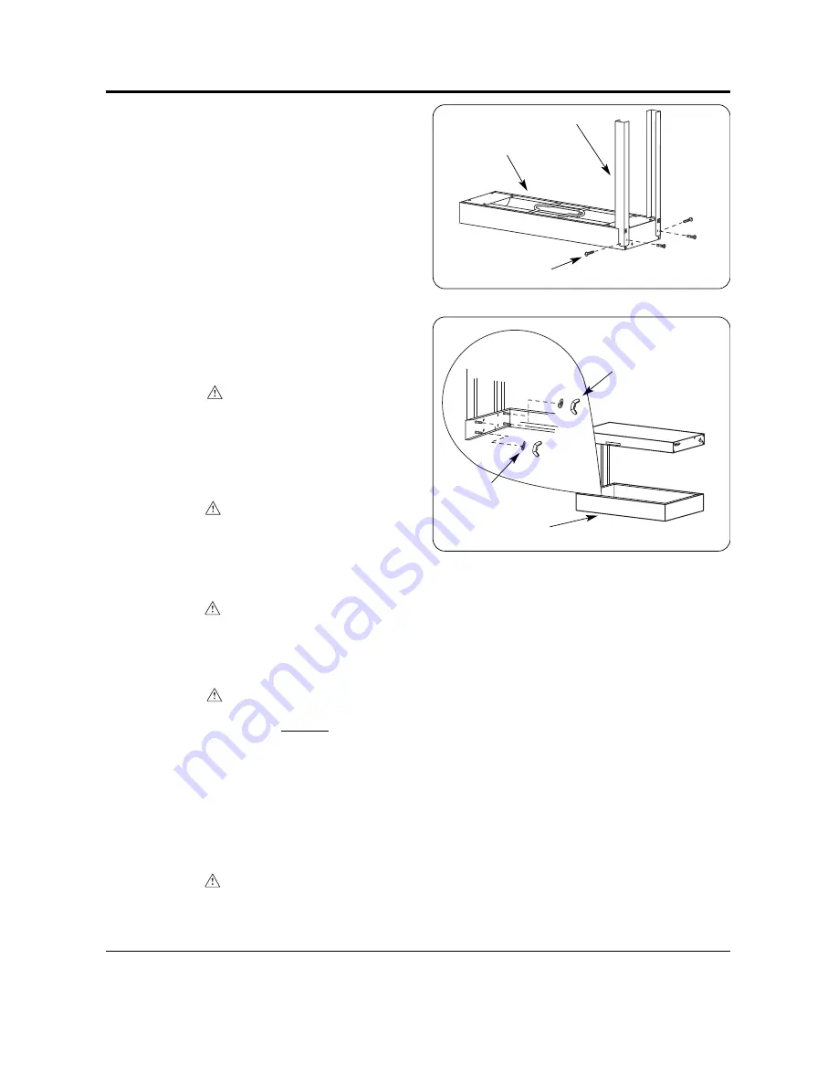
Figure 13. Assembly of Top Housing and Leg Bracket
Figure 14. Assembly of Top Housing with Leg Bracket to
Base Unit
CAUTION HOT
GLO-RA
Y
FOODW
ARMER
HATCO CORP
. MIL
WAUKEE, WI U
.S.A.
CAUTION MAXIMUM LAMP
SIZE 60W
.
ON
OFF
NOTE: A Phillips Screwdriver is required for this
assembly.
1. Remove top housing, leg brackets, and base unit
from carton and set parts on a non-scratch
surface.
2. Remove all packaging materials from unit.
3. Position the top housing, element side up, on a
non-scratch surface.
4. Using the four screws provided attach both leg
brackets to the top housing. (See Figure 13.)
5. Secure top assembly to base unit using lock
washers and wing nuts provided. (See
Figure 14.)
6. Place unit in desired location.
Top Housing
Screw
Base Unit
Lock Washer
Wing Nut
Leg Bracket
Total Restaurant Supply - https://totalsupply1.com - Toll Free 1-800-944-9304 - Local 507-288-9454
2940 Hwy 14 W, Rochester, MN 55901


