Form No. GR2AM-1116
17
English
INSTALLATION
Models
Width
(A)
Width
(B)
Height
(C)
Depth
(D)
Height
(E)
RMB2-1R 10-1/8″
(257 mm)
11″
(279 mm)
5-1/2″
(140 mm)
4-1/4″
(109 mm)
4-5/8″
(116 mm)
RMB2-2R 13-1/8″
(333 mm)
14″
(356 mm)
5-1/2″
(140 mm)
4-1/4″
(109 mm)
4-5/8″
(116 mm)
Models
Opening Cutout
Dimensions
Screw Hole
Dimensions
(A)
(B)
(C)
(D)
(E)
RMB2-1R
4-3/4″
(121 mm)
10-1/8″
(257 mm)
1-1/8″
(29 mm)
2-1/2″
(64 mm)
10-7/16″
(265 mm)
RMB2-2R
4-3/4″
(121 mm)
13-1/8″
(333 mm)
1-1/8″
(29 mm)
2-1/2″
(64 mm)
13-7/16″
(341 mm)
Remote Control Enclosure — RMB2 Series
RMB2 Series remote control enclosures allow multiple strip
heaters to be wired to and controlled by a single enclosure. The
total amp draw of all connected strip heaters cannot exceed the
rating of the remote control enclosure. Consult the factory for
information regarding the proper RMB2 Series remote control
enclosure for a specific application. Refer to the Instruction
Sheet included with the enclosure for installation information.
RMB2 Series Dimensions
Top View
A
B
C
E
Front View
Side View
D
Cutout Dimensions — RMB2
NOTE: Make sure the width of the cutout does not exceed the
dimension given for each size enclosure.
B
A
E
D
C
Dimensions — RMB2
RMB2 Series Cutout Dimensions
2. Secure the RMB to the mounting surface using appropriate
screws or fasteners.
• Use the mounting flange on each end of the RMB.
NOTE: Sizing of the power supply wire leads and upstream
overcurrent protection must conform with National
Electric Code (NEC) requirements as well as all local
codes.
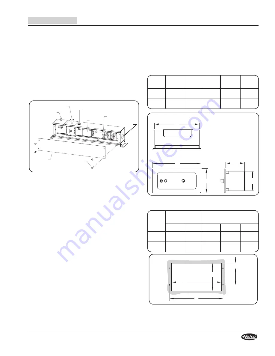
3. Remove the wiring access cover on bottom of the control
enclosure by removing screws and sliding cover off.
4. Identify and remove the appropriate knockouts from the
control enclosure for the electrical connections.
5. Attach conduit connectors to the knockouts in the control
enclosure.
Removing Wiring Access Cover
6. Make the electrical connections between the unit and the
output terminals on the terminal block or wire leads inside
the control enclosure. Refer to the wiring diagrams
included with the unit and the RMB control enclosure.
NOTE: To ground the RMB, use either a separate ground wire,
metallic conduit, or other locally accepted method in
accordance with the National Electric Code (NEC) or
Canadian Electric Code (CEC).
7. Tie all ground leads (green and/or green/yellow leads)
together and terminate with a UL Listed wire nut.
8. Make the electrical connections between the power supply
and the input terminals on the terminal block or wire leads
inside the control enclosure. Refer to the wiring diagram
included with the RMB control enclosure.
NOTE: Verify which wire leads from the foodwarmer are for
phase, neutral, and/or lighting connections, as
applicable.
9. Make sure all wire connections are tight, and secure both
conduit runs to the conduit connectors.
10. Reinstall the wiring access cover on bottom of the control
enclosure.
11. Turn on power at the fused disconnect switch/circuit
breaker, turn on the unit, and test operation.
Toggle Switch
Infinite Control
Wiring
Access
Cover
Knockout
Terminal Block
Cover
Screw
Relay
Indicator
Light


