background image

Form No. GR2AM-1116

21

English

OPTIONS AND ACCESSORIES

Infinite Switch

Use the following procedure to install an infinite switch. An

infinite switch needs to be installed into an approved electrical

box/enclosure (not supplied) by a qualified electrician.

ELECTRIC  SHOCK  HAzARD:  Turn  OFF  power  switch,

disconnect unit from power source, and allow unit to cool

before performing any cleaning, adjustments, or maintenance.

To  prevent  premature  failure  of  components  due  to

excessive heat, remote mounted control switches must be

installed outside the strip heater heat zone.

1. Verify unit is off and disconnected from the power source.
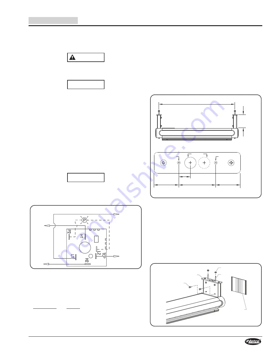
2. Install the infinite switch. Refer to the wiring diagram for

proper  electrical  connections.  Make  sure  the  switch  is

installed with the “H1” terminal oriented on top. This will

ensure that the switch functions match the markings on

the switch label.

• Power In: L1 and L2 (for 100V and 120V units, L2 is

neutral)

• To Heating Element: H1 and H2

NOTE: The  terminals  on  the  infinite  switch  are  specially

designed, high-temperature rated terminals that do not

require solder connections.

The infinite switch must be installed using the terminals

and  wires  supplied  with  the  switch.  Failure  to  use  the

supplied Genuine Hatco Replacement Parts will void all

warranties and may damage the equipment.

Infinite Switch Wiring Diagram (rear view)

NOTE: Make sure the switch is installed with the “H1” terminal

oriented on top (“12 o’clock” position), as shown above.

This will ensure that the switch functions match the

markings on the switch label.

Infinite Switch Kit Part Numbers

Part Number

Voltage

R02.19.160.00

100 volt

R02.19.018.00

120 volt

R02.19.017.00

208 volt

R02.19.019.00

240 volt

WARNING

NOTICE

NOTICE

LINE

100V

120V

208V

240V

NEUTRAL

NEUTRAL

208V

240V

LOAD

Overhead Mounts

Overhead mounts are available in lieu of 14″ (356 mm) standard

legs. This is a factory installed option, not available for retrofit.

Use the following procedure to install a unit to the ceiling.

1. With  overhead  mount  covers  removed,  attach  overhead

mounts on each end of unit using supplied screws.

2. Mark the holes on the ceiling using the “Mounting Dimensions”

illustration below. All models have one conduit hole except

models listed below.

• Two Conduit Holes: All Tandem units, 

GR2AH-XXD (60–84″), GR2AL-XXD (84″), and

GR2AHL-XXD (60–84″)

Mounting Dimensions

3. Drill the marked holes.

• The bolt holes are 1/4" (6 mm) diameter.

• The conduit hole(s) are 1" (25 mm) diameter.

4. Place the unit into position over the mounting holes with

the electrical conduit(s) positioned through the channel and

center mounting hole(s). 

5. Secure the unit to the ceiling with supplied 1/4" x 1-1/2"

(6 x 38 mm) hex bolts and nuts.

6. Install overhead mount covers onto overhead mounts by

snapping into place.

Installing Overhead Mount

Overall Width 

minus

2-7/32'' (56 mm)

Front View

Top View - Mounting Flange

2''

(51 mm)

15/16''

(24 mm)

Conduit

Holes

3''

(76 mm)

2''

(51 mm)

Bolt Hole

Bolt Hole

4''

(102 mm)

Screws

Overhead Mount

Nut
Bolt

Overhead

Mount

Cover

Summary of Contents for GR2A-18

Page 1: ...o al menos que haya le do y comprendido el contenido de este manual Cualquier falla en el seguimiento de las instrucciones contenidas en este manual puede resultar en un serio lesi n o muerte Este man...

Page 2: ...ted for maximum durability attractive appearance and optimum performance Every unit is inspected and tested thoroughly prior to shipment Important Owner Information 2 Introduction 2 Important Safety I...

Page 3: ...N NOTICE WARNING ELECTRIC SHOCK HAzARD Units supplied without an electrical plug require a hardwired connection to on site electrical system Connection must be properly grounded and of correct voltage...

Page 4: ...rared Foodwarmers are ideal for holding hot food on pass through holding areas and waitress pick up stations All Designer models are constructed of aluminum For self serve applications models may be e...

Page 5: ...6 7 64 lbs 29 kg 208 800 3 9 64 lbs 29 kg 240 800 3 3 64 lbs 29 kg GR2A 54 120 925 7 7 74 lbs 34 kg 208 925 4 5 74 lbs 34 kg 240 925 3 9 74 lbs 34 kg GR2A 60 120 1050 8 8 82 lbs 37 kg 208 1050 5 1 82...

Page 6: ...240 1100 4 6 64 lbs 29 kg GR2AH 54 120 1250 10 4 74 lbs 34 kg 208 1250 6 0 74 lbs 34 kg 240 1250 5 2 74 lbs 34 kg GR2AH 60 120 1400 11 7 82 lbs 37 kg 208 1400 6 7 82 lbs 37 kg 240 1400 5 8 82 lbs 37...

Page 7: ...5 9 7 74 lbs 34 kg 120 208 1165 6 5 74 lbs 34 kg 120 240 1165 5 9 74 lbs 34 kg GR2AL 60 120 1350 11 3 83 lbs 38 kg 120 208 1350 7 6 83 lbs 38 kg 120 240 1350 6 9 83 lbs 38 kg GR2AL 66 120 1460 12 3 93...

Page 8: ...4 lbs 34 kg 120 240 1490 7 2 74 lbs 34 kg GR2AHL 60 120 1700 14 2 83 lbs 38 kg 120 208 1700 9 2 83 lbs 38 kg 120 240 1700 8 3 83 lbs 38 kg GR2AHL 66 120 1860 15 5 93 lbs 42 kg 120 208 1860 10 0 93 lbs...

Page 9: ...77 lbs 35 kg 208 1600 7 7 77 lbs 35 kg 240 1600 6 7 77 lbs 35 kg GR2A 54D 120 1850 15 4 88 lbs 40 kg 208 1850 8 9 88 lbs 40 kg 240 1850 7 7 88 lbs 40 kg GR2A 60D 120 2100 17 5 97 lbs 44 kg 208 2100 10...

Page 10: ...77 lbs 35 kg GR2AH 54D 120 2500 20 1 88 lbs 40 kg 208 2500 12 0 88 lbs 40 kg 240 2500 10 4 88 lbs 40 kg GR2AH 60D 120 2800 23 3 97 lbs 44 kg 208 2800 13 5 97 lbs 44 kg 240 2800 11 7 97 lbs 44 kg GR2A...

Page 11: ...s 41 kg 120 208 2090 10 9 91 lbs 41 kg 120 240 2090 9 7 91 lbs 41 kg GR2AL 60D 120 2400 20 100 lbs 45 kg 120 208 2400 12 6 100 lbs 45 kg 120 240 2400 11 3 100 lbs 45 kg GR2AL 66D 120 2620 21 8 110 lbs...

Page 12: ...0 2740 22 1 91 lbs 41 kg 120 208 2740 14 0 91 lbs 41 kg 120 240 2740 12 4 91 lbs 41 kg GR2AHL 60D 120 3100 25 8 100 lbs 45 kg 120 208 3100 16 0 100 lbs 45 kg 120 240 3100 14 2 100 lbs 45 kg GR2AHL 66D...

Page 13: ...7 1 2 191 mm Sneeze Guard 14 356 mm Sneeze Guard 11 7 8 302 mm Dimensions NOTE Units with 7 1 2 Sneeze Guards add 5 3 4 146 mm per side to Depth B Units with 14 Sneeze Guards add 11 7 8 302 mm per si...

Page 14: ...dual food warmers GR2A XXD Series less than 27 689 mm above combustible surfaces e Do not install high wattage dual food warmers GR2AH XXD and GR2AHL XXD Series less than 32 813 mm above combustible...

Page 15: ...m spacing of 3 76 mm between units Non Adjustable Stand Cover Bolt Nut Electrical Requirements Foodwarmers equipped with incandescent lights that require a circuit breaker larger than 20 amps for the...

Page 16: ...easing the life span of the controls All models are built in accordance with UL standards with switches indicator lights and wiring Consult the factory for type and location of RMB Series controls for...

Page 17: ...lectric Code NEC requirements as well as all local codes 3 Remove the wiring access cover on bottom of the control enclosure by removing screws and sliding cover off 4 Identify and remove the appropri...

Page 18: ...e lights Indicator Light Illuminates when power is on shuts off when power is off NOTE Toggle switches cannot be used on circuits that exceed 15 amps Infinite controls cannot be used on circuits that...

Page 19: ...susceptible to soil accumulation IMPORTANT DO NOT use paper towel or glass cleaner to clean polycarbonate surfaces Paper towel and glass cleaner may scratch the material Wipe off polycarbonate surfac...

Page 20: ...t breaker tripped Reset circuit breaker If circuit breaker continues to trip contact Authorized Service Agent or Hatco for assistance Control switches burn out Remote control enclosure is mounted too...

Page 21: ...alled with the H1 terminal oriented on top 12 o clock position as shown above This will ensure that the switch functions match the markings on the switch label Infinite Switch Kit Part Numbers Part Nu...

Page 22: ...freezing or Product misuse tampering or misapplication improper installation or application of improper voltage 2 LIMITATION OF REMEDIES AND DAMAGES Hatco s liability and Buyer s exclusive remedy here...

Page 23: ...pes chauffantes Designer Glo Ray de Hatco sont le r sultat de longues recherches et de nombreux essais sur le terrain Les mat riaux utilis s ont t s lectionn s pour un maximum de durabilit une belle a...

Page 24: ...alt rant son apparence et la rendant vuln rable l accumulation de salet AVIS ATTENTION AVERTISSEMENT DANGER DE D CHARGE LECTRIQUE Units supplied without an electrical plug require a hardwired connecti...

Page 25: ...urriture dans les zones passantes et les zones de r cup ration des plats par les serveurs Tous les mod les Designer sont fabriqu s en aluminium Pour les espaces de vente en libre service les mod les p...

Page 26: ...5 2 8 24 kg 53 lbs GR2A 48 120 800 6 7 29 kg 64 lbs 208 800 3 9 29 kg 64 lbs 240 800 3 3 29 kg 64 lbs GR2A 54 120 925 7 7 34 kg 74 lbs 208 925 4 5 34 kg 74 lbs 240 925 3 9 34 kg 74 lbs GR2A 60 120 105...

Page 27: ...00 5 3 29 kg 64 lbs 240 1100 4 6 29 kg 64 lbs GR2AH 54 120 1250 10 4 34 kg 74 lbs 208 1250 6 0 34 kg 74 lbs 240 1250 5 2 34 kg 74 lbs GR2AH 60 120 1400 11 7 37 kg 82 lbs 208 1400 6 7 37 kg 82 lbs 240...

Page 28: ...29 kg 64 lbs GR2AL 54 120 1165 9 7 34 kg 74 lbs 120 208 1165 6 5 34 kg 74 lbs 120 240 1165 5 9 34 kg 74 lbs GR2AL 60 120 1350 11 3 38 kg 83 lbs 120 208 1350 7 6 38 kg 83 lbs 120 240 1350 6 9 38 kg 83...

Page 29: ...08 1490 8 0 34 kg 74 lbs 120 240 1490 7 2 34 kg 74 lbs GR2AHL 60 120 1700 14 2 38 kg 83 lbs 120 208 1700 9 2 38 kg 83 lbs 120 240 1700 8 3 38 kg 83 lbs GR2AHL 66 120 1860 15 5 42 kg 93 lbs 120 208 186...

Page 30: ...kg 66 lbs GR2A 48D 120 1600 13 3 35 kg 77 lbs 208 1600 7 7 35 kg 77 lbs 240 1600 6 7 35 kg 77 lbs GR2A 54D 120 1850 15 4 40 kg 88 lbs 208 1850 8 9 40 kg 88 lbs 240 1850 7 7 40 kg 88 lbs GR2A 60D 120...

Page 31: ...lbs GR2AH 54D 120 2500 20 1 40 kg 88 lbs 208 2500 12 0 40 kg 88 lbs 240 2500 10 4 40 kg 88 lbs GR2AH 60D 120 2800 23 3 44 kg 97 lbs 208 2800 13 5 44 kg 97 lbs 240 2800 11 7 44 kg 97 lbs GR2AH 66D 120...

Page 32: ...AL 54D 120 2090 17 4 41 kg 91 lbs 120 208 2090 10 9 41 kg 91 lbs 120 240 2090 9 7 41 kg 91 lbs GR2AL 60D 120 2400 20 45 kg 100 lbs 120 208 2400 12 6 45 kg 100 lbs 120 240 2400 11 3 45 kg 100 lbs GR2AL...

Page 33: ...36 kg 79 lbs GR2AHL 54D 120 2740 22 1 41 kg 91 lbs 120 208 2740 14 0 41 kg 91 lbs 120 240 2740 12 4 41 kg 91 lbs GR2AHL 60D 120 3100 25 8 45 kg 100 lbs 120 208 3100 16 0 45 kg 100 lbs 120 240 3100 14...

Page 34: ...Si l appareil est quip de pare haleine de 19 05 cm 7 1 2 ajouter 14 6 cm 5 3 4 de chaque c t la profondeur B Si l appareil est quip de pare haleine de 35 6 cm 14 ajouter 30 2 cm 11 7 8 de chaque c t l...

Page 35: ...AHL XXD moins de 81 3 cm 32 au dessus d une surface combustible f Installez toutes les rampes chauffantes Designer une distance minimale de 15 2 cm 6 par rapport aux murs ou surfaces adjacentes combus...

Page 36: ...s de lumi res incandescentes qui n cessitent un disjoncteur de plus de 20 amp res pour l l ment chauffant doivent avoir un disjoncteur s par pour les lumi res incandescentes de 20 amp res ou moins Pou...

Page 37: ...lumineux S allume lorsque le courant est allum s teint lorsque le courant est teint NOTA Les interrupteurs bascule ne peuvent pas tre utilis s sur des circuits qui d passent 15 amp res Le contr le inf...

Page 38: ...nt Essuyez les surfaces en polycarbonate l aide d un chiffon doux propre et humide AVERTISSEMENT AVIS 1 Mettre l appareil hors tension et laisser refroidir l appareil 2 Essuyez l ensemble des surfaces...

Page 39: ...disjoncteur Si le disjoncteur continue de se d clencher contactez un agent de service agr ou Hatco pour obtenir de l aide Les interrupteurs de commande ont grill Le bo tier de contr le distance est in...

Page 40: ...propri es Utilisez la bride de montage chaque extr mit du bo tier RMB D E C B A Vue du dessus Vue de face Vue de c t NOTA Le dimensionnement des c bles d alimentation et la protection contre les surte...

Page 41: ...ent unique L amp rage total de tous les r chauffeurs de bande connect s ne peut pas exc der la notation du compartiment de contr le distance Consultez l usine pour des informations concernant le compa...

Page 42: ...eur et laissez refroidir l unit avant d effectuer toute op ration de nettoyage de r glage ou d entretien Pour viter une d faillance pr matur e des composants due une chaleur excessive les interrupteur...

Page 43: ...les appareils en tandem GR2AH XXD 1524 2133 6 mm 60 84 GR2AL XXD 2133 6 mm 84 et GR2AHL XXD 1524 2133 6 mm 60 84 Dimensions de montage 3 Percez les trous marqu s Les trous de vissage ont un diam tre d...

Page 44: ...TRES ATTEINTES AUX DROITS DE LA PROPRI T INTELLECTUELLE Sans restreindre la port e g n rale des nonc s pr c dents CES GARANTIES NE COUVRENT PAS Ampoules d clairage incandescence enduites lumi res fluo...

Page 45: ...Form No GR2AM 1116 45 English NOTES...

Page 46: ...Form No GR2AM 1116 46 English NOTES...

Page 47: ...Form No GR2AM 1116 47 English NOTES...

Page 48: ...vice St Louis 314 535 2222 NEBRASKA Anderson Electric Omaha 402 341 1414 NEVADA Burney s Commercial Las Vegas 702 736 0006 Hi Tech Commercial Service N Las Vegas 702 649 4616 NEW JERSEy Jay Hill Repai...

Reviews: