
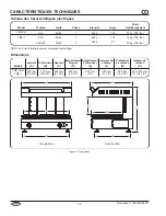


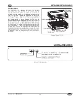
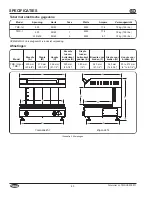


N.dipubblicazioneTMSCEM-0911
51
INSTALLAzIONE
Installazione a parete
1. Installarelastaffaperilmontaggioaparetefornitacon
l’unitàsuunasuperficiesolidanoninfiammabileusando
glielementidifissaggioadatti.Sullastaffaperilmontaggio
aparetecisonocinquefori.
• Assicurarsicheglielementidifissaggiosianoidoneialla
superficiediinstallazioneealpesodell’unità.
• Collocare l’unità direttamente sotto una cappa di
aspirazionesepossibile.Inquestomodosigarantirà
l'aspirazione totale del vapore prodotto durante la
cottura.
• Assicurarsichel'unitàsiaaun'altezzaadeguatainun
postopraticoperl'utilizzo.
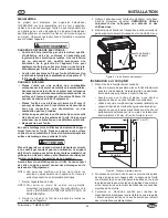
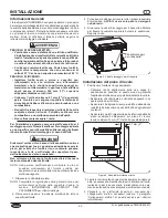
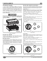
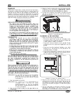
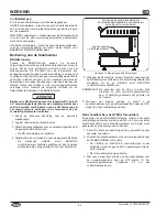
2. Allinearelefessuredimontaggiosulretrodell’unitàconi
gancisullastaffaperilmontaggioaparete.Agganciare
l’unità.
Figura6.Fessuredimontaggiosulretrodell’unità
3. Chiedere a un elettricista esperto di occuparsi dei
collegamenti elettrici necessari (vedere il paragrafo
“Collegamenti elettrici” di questa sezione per ulteriori
informazioni).
Collegamenti elettrici
Il fornello portatile THERM-MAX deve essere cablato
all’alimentazioneelettricaoavereilcavoe/olaspinaadeguati
installati.
PERICOLO DI SCOSSA ELETTRIC:
• Le unità fornite senza una spina elettrica richiedono
l'installazione sul posto della spina adeguata. La spina
deve essere messa a terra in modo corretto e avere la
tensione, le dimensioni e la configurazione corrette
riportate nelle specifiche dell'unità. Contattare un
elettricista qualificato per determinare e installare la
spina elettrica appropriata.
• Le unità fornite senza una spina e un cavo elettrici
richiedono l'installazione sul posto della spina e del
cavo adeguati o di un collegamento cablato al sistema
elettrico in loco. Il collegamento deve essere messo a
terra in modo adeguato e avere la tensione, le
dimensioni e la configurazione corretti riportati nelle
specifiche dell'unità. Contattare un elettricista
qualificato per determinare e installare il collegamento
elettrico appropriato.
Fessure di montaggio
AVVERTENZA
• quando si installa un’unità cablata, è necessario
inserire un commutatore a 2 o 3 poli (a seconda
dell’unità) tra l’unità e l’alimentazione elettrica
principale. Il commutatore deve avere una capacità
adeguata e contatti con una distanza di apertura minima
di 3 mm (1/8").
• L’unità deve essere collegata a un sistema
equipotenziale conforme alle normative elettriche in
vigore.
Per evitare danni al dispositivo, assicurarsi che tensione e
frequenza dell'alimentazione elettrica corrispondano a
quelle indicate sulla targhetta dei dati tecnici.
Collegamento cablato
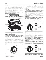
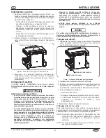
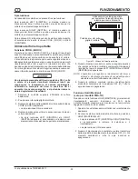
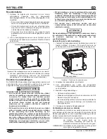
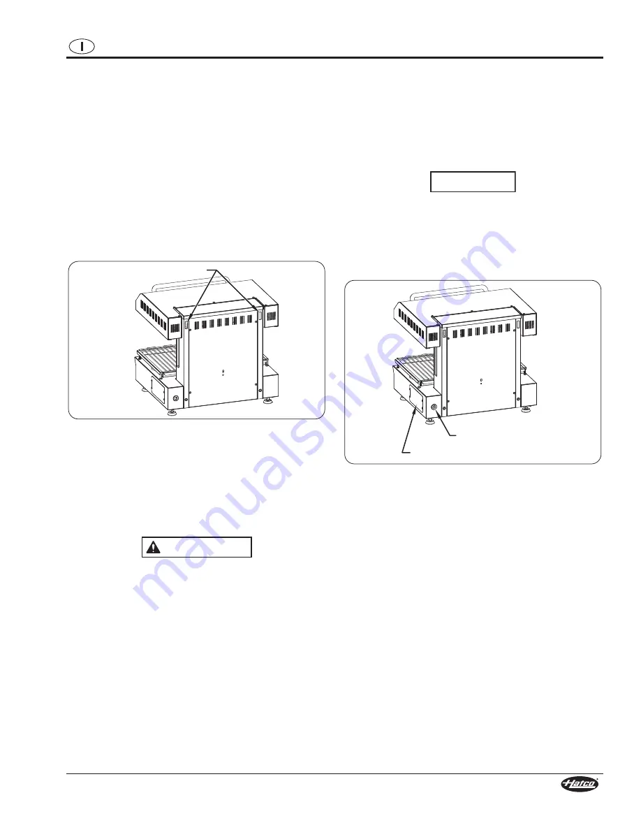
1. Rimuovereilpannellodiaccessoperesporrel’areadella
presa di ingresso dell’unità. Si trova sul lato posteriore
destrodell’unitàguardandoicomandi.
Figura7.Posizionedellapresadialimentazione
2. Individuarelamorsettieraall’internodell’unità.
3. Portarelederivazionielettrichedauninterruttoredicircuito
adeguatamente dimensionato o dall’interruttore di
sconnessionetramitelapresadialimentazionesull’unità.
4. Fareicollegamentinecessari.
• Usaresolofilidirame.
• Stringereicollegamentiadalmeno4,25Nm(40inch-lb).
• Vicinoaimorsettielettricic’èunavitedimessaaterra.
Collegarvi un conduttore di messa a terra
dell’apparecchio.
5. Ricollocareefissareilpannellodiaccesso.
Collegamento cavo e spina
Sulle unità fornite con un cavo elettrico, collegare la spina
appropriataalcavo.Assicurarsichelaspinasiaadeguataal
caricospecificoechecombaciconunapresaadeguata.
NOTA: L’etichetta delle specifiche è posizionata sul lato
dell’unità vicino alla presa di alimentazione. Vedere
l’etichetta per verificare le informazioni elettriche
sull’unità.
NOTA: La spina e la presa devono essere messe a terra
secondo le normative correnti.
Presa di alimentazione
Pannello di accesso
AVVISO


