INSTALLATION
6
FormNo.TMSCEM-0911
General
THERM-MAX Salamandersareshippedwithmostcomponents
pre-assembled. Care should be taken when unpacking the
shipping carton to avoid damage to the unit and the
componentsenclosed.Thesalamandercanbeplacedona
countertopormountedtoabrickorcementwall.Thefollowing
installationinstructionsmustbeperformedbeforeoperatingthe
salamander.
ELECTRIC ShOCk hAzARD:
• Unit must be installed by a qualified electrician.
Installation must conform to all local electrical codes.
Installation by unqualified personnel will void unit
warranty and may lead to electric shock or burn, as well
as damage to unit and/or its surroundings.
• Unit is not weatherproof. Locate unit indoors where
ambient air temperature is a minimum of 21°C (70°F)
and a maximum of 29°C (85°F).
FIRE hAzARD:
• Install unit on and around non-combustible surfaces
with non-combustible construction only. Ensure
surface construction has no combustible material
against underside. In all cases, such construction
shall extend at least 305 mm (12″) beyond equipment
on all sides.
• Locate unit a minimum of 51 mm (2″) from any walls. If
safe distances are not maintained, discoloration or
combustion could occur.
• Do not obstruct air intake openings or air exhaust
openings on outer housing of unit. Unit combustion or
malfunction may occur.
• Do not place anything on top of unit.
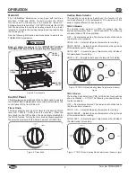
For wall mounting, use special wall mount bracket
provided with unit only. Secure wall mount bracket to a
solid, non-combustible surface using appropriate hardware
for mounting surface and weight of unit.
Locate unit at proper counter height in an area that is
convenient for use. Location should be level to prevent unit
or its contents from falling accidentally and strong enough
to support the weight of the unit and contents.
Do not place anything on top of unit; doing so may subject
personnel to injury or damage unit.
NOTE: A qualified person must check possible placements of
the salamander to ensure that the proper electrical
supply line is available.
1. Removetheunitfromtheshippingcarton.
NOTE: To prevent delay in obtaining warranty coverage,
complete online warranty registration. See the
IMPORTANTOWNERINFORMATION
section for details.
2. Removetapeandprotectivepackagingfromallsurfaces
ofunit.
3. Cleantheunitthoroughlytoremoveallprotectiveindustrial
grease.
NOTICE:
Use non-abrasive cleaners and cloths
only.
WARNING
CAUTION
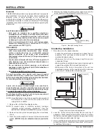
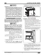
4. Removethetransportlockingscrewusedtosecurethe
upperhousingduringshipping.Discardthescrew.
Figure4.TransportlockingScrew
Countertop Installation
1. Placetheunitinthedesiredlocation.
• locatetheunitdirectlyunderneathanexhausthoodif
possible. This will ensure total suction of steam
producedduringcooking.
• Makesuretheunitisattheproperheightinanarea
convenientforuse.
• Makesurethecountertopislevelandstrongenoughto
supporttheweightoftheunitandfoodproduct.
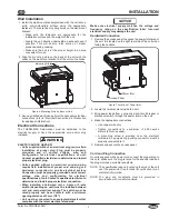
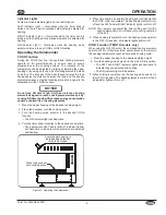
• Make sure all the feet on the bottom of the unit are
positionedsecurelyonthecountertopwithaminimum
of51mm(2″)betweentheunitandanywall.
Figure5.MinimumDistanceRequirement
2. leveltheunitbyturningthelevelingfeetoneachleg,if
necessary.Whenlookingatthebottomoftheunit,turning
thefeetcounterclockwisewilllengthenthelegs,andturning
thefeetclockwisewillshortenthelegs.
3. Haveaqualifiedelectricianperformthenecessaryelectrical
connections(referto“ElectricalConnections”inthissection
foradditionalinformation).
Transport Locking
Screw
W
all
Countertop
51 mm (2″)


