background image

SETTINGS PROGRAMMING

Programming the controller is done using the "SETUP", "LEARN" buttons, LED diodes and 4

function switches located on the controller board.

Programming can only take place when the gate is in stop state. If we start programming

the controller during the auto-closing time countdown, the countdown will be stopped and to

close the gate, press the SBS button or the remote control transmitter.

AUTOCLOSE FUNCTION

After stopping the gate, after the OPEN signal, the time set by the user is counted, after
which the CLOSING will take place. The light shines during the countdown. For the user's

safety, photocells are required (so that the gate does not close when there is an obstacle in
its light!). Additionally, when the PHOTO CLOSE function is on, the photocells will shorten

the auto-closing time and after detecting the passage, the gate will close after 5 seconds.
Each detected trip will countdown this time again. If the gate is in the fully open position,

each signal trying to activate it in the opening direction will start the countdown of the auto-
closing time.

ATTENTION! Stopping the gate with a transmitter or control button during closing stops
the countdown and to close the gate, press the control button again - you can use it when

you need to leave the gate open for some time.

To 

turn on

 the function, set the 

AUTO CL

switch to the 

ON

 position.


To 

disable

 the function, set the 

AUTO CL

switch to the 

OFF

 position.


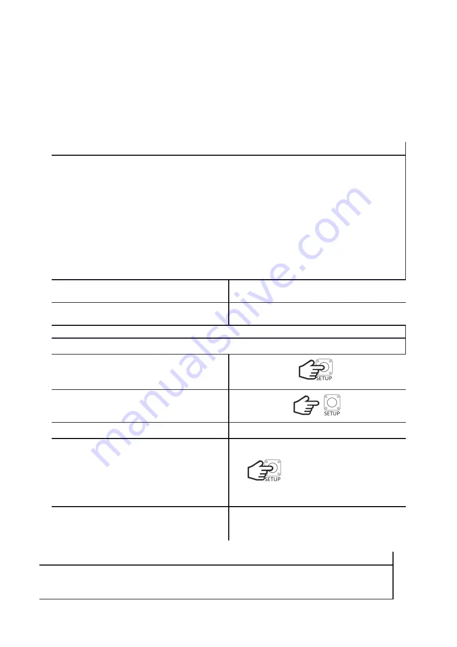
SET THE AUTO-CLOSE TIME

We set it in the range from 15s to 25 minutes in steps of 15s. By default: 6min

Hold down the 

SETUP

 button for less than

3s. When the button is pressed, the 

LED

lights up.


Release the 

SETUP

 button.

The 

LED

 will flash rapidly.

Within 5s, start setting the time.

Press 

SETUP x 

times. One press corresponds

to 15s. Each press is signaled by the lighting

of the diode. If the button is not pressed

within these 5 seconds, the controller will

set the default time.


After 3s from the last press, the 

LED

 will

flash 3 times. The controller will remember

the settings and return to normal operation.


TRAFFIC LIGHTS

While the gate is moving, the light signaling can work in two modes: as a movement signal
(it flashes slowly when the gate opens, and quickly when the gate closes) or a signal for full

opening (

DEFAULT SETTINGS

). Additionally, it lights up during the countdown of the auto-

Summary of Contents for 535Y

Page 1: ...HATO 535Y AUTOMATIC BARRIER OPERATING MANUAL...

Page 2: ...ON electronics 14 DIMENSIONS 14 DRIVER ASSEMBLY 15 CONNECTION DIAGRAM 18 SETTINGS PROGRAMMING 19 1 WARRANTY CONDITIONS 24 Congratulations on your purchase of HATO 535Y automatic barrier and welcome to...

Page 3: ...h the applicable regulations in the field of electrical equipment operation and in accordance with health and safety regulations Do not connect the drive to the power supply earlier than specified in...

Page 4: ...vices helps to protect the environment and ensures that disposal is done in a way that protects human health and the environment This note also applies to waste batteries and accumulators DECLARATION...

Page 5: ...ions 360 230 1050 Max arm length 5m Weight 60kg Number of cycles per hour 200 LIST OF ELEMENTS No Description Quantity 1 Barrier 1 2 Mounting plate for the barrier arm 1 3 Barrier mounting cover 1 4 H...

Page 6: ......

Page 7: ...rs drill CORDS power cord 1 5mm2 signal cord 0 5mm2 FOUNDATION When the foundation is poured under the barrier a PVC pipe should be placed in it min 12mm diameter This way we can secure the cords brou...

Page 8: ...spacing 150mm x 260mm To do this place the barrier on the foundation and mark the holes Then move the barrier and drill the holes Put expansion plugs into the drilled holes or instert the screws into...

Page 9: ...j lub zamkni tej INITIAL ADJUSTMENT Use the handle to manually set the barrier in the opening position Loosen the M4 screw of the opening cam and turn the cam until the green indicator light for limit...

Page 10: ...rwszym otworze 5 6m w sytuacji gdy szlaban jest kr tszy ni 5m nale y zamontowa spr yn w odpowiedni otw r To do this you need to Loosen the spring bringing the barrier to the open position Loosen the n...

Page 11: ...LB11SZ complies with the directives EMC 2014 30 UE LVD 2014 35 UE RED 2014 53 UE ROHS 2011 65 UE MD 2006 42 UE declares that the equipment type HELB11 is in compliance with Directives EMC 2014 30 UE L...

Page 12: ...Manual Keep this installation and operating manual in an accessible place Use the product in accordance with its intended use Observe and comply with the health and safety regulations and standards i...

Page 13: ...an aggressive atmosphere Carry out inspection and maintenance work at least every 6 months INSTALLATION Gates barriers that are automatically opened with a drive must meet the requirements of applicab...

Page 14: ...MODE OF ACTION The drive is controlled by means of a transmitter button programmed in eLB11SZ or a bell button of the SBS sequence control In both cases the operation consists in carrying out the step...

Page 15: ...ke sure that all safety recommendations are met Any installation work may only be performed by qualified personnel Electrical installation and connection of electronic devices may only be performed by...

Page 16: ...er additional protection against crushing in the door clearance They must be connected in series with the photocells Photocells 12 24VDC plus power for photocell 13 COM minus power for photocell 13 CO...

Page 17: ...connecting it Fluorescent lamps must not be used as traffic lights 4 7 Power connection The last stage of connection is to connect the controller power supply connect in turn the wires 2 PE protectiv...

Page 18: ...f the entire automatic unit and all connected safety signaling and control elements limit switches photocells edge strip light signaling etc 11 Set the available additional functions 12 Train all user...

Page 19: ...auto closing time ATTENTION Stopping the gate with a transmitter or control button during closing stops the countdown and to close the gate press the control button again you can use it when you need...

Page 20: ...ress the SETUP button briefly within 3 seconds After 3s from the last press the LED will flash 3 times The controller will remember the settings and return to normal operation WARNING SIGNALS The warn...

Page 21: ...O CL switch to OFF LIMIT SWITCH TYPE The controller works as a standard with electromagnetic switches supplied with 24Vdc voltage and with 24Vdc voltage output signal Depending on whether the voltage...

Page 22: ...nk and the receiver will return to normal operation REMOTE PROGRAMMING OF TRANSMITTERS eLB11SZE Remote programming of transmitters takes place when the barrier is fully open and a 4 channel transmitte...

Page 23: ...NOTES...

Page 24: ...ntor Defects revealed during this time will be removed free of charge The repair will be made as soon as possible not exceeding 14 days from the date of delivery of the device to the HATO POLSKA Servi...

Page 25: ...damage to devices previously dismantled or repaired by unauthorized persons d devices with a damaged illegible incorrectly filled in warranty card or a broken seal e damage to devices used intensively...

Page 26: ......

Page 27: ...HATO TRADE SP ZOO ul eromskiego 1 41 205 Sosnowiec POLAND tel 032 785 25 42 www hato com pl DISTRIBUTOR SELLER...

Reviews: