background image


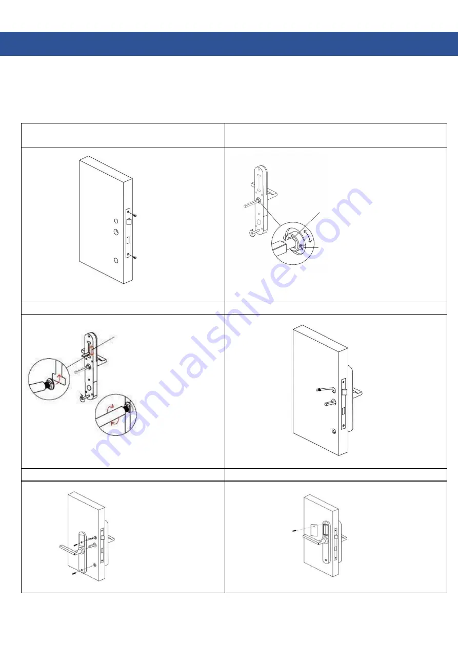
ASSEMBLY


Be careful when passing the cable through the door so as not to damage it. A sufficiently large hole or a separate 

channel should be made in order to pass the cable and arrange its excess inside the door. The wire connecting 

the two parts of the lock must not be led through the pin channel. Damage resulting from short circuit and 

destruction of wires is not subject to warranty repair! 


 Step 1: Install the mortise lock 

 Step 2: Install the square and hexagonal 
shaft housing 


If the handle is to be facing 
left, align the triangle sign to 
the left. If the handle is to be 
facing right, align the triangle 
sign to the right. 


Insert the pin into a hole in the 
plate in order to prevent the pin 
from falling out. 

 Step 3:  Mounting bolt installation location 

 Step 4: Mount the front panel 


The mounting 
screw casing can 
be adjusted from 
55mm to 100mm 
from square shaft. 
 
Try out first. 
Mount the screw into  
the old mounting hole. 


 Step 5: Mount the back panel 

 Step 6: Put batteries in 


Summary of Contents for TA-311

Page 1: ...1 HATO TA 311 ELECTRONIC ESCUTCHEON OPERATING MANUAL...

Page 2: ...CONTENTS ZALECENIA I RODKI OSTRO NO CI DOTYCZ CE BEZPIECZE STWA 3 DANE TECHNICZNE 4 LISTA ELEMENT W 4 INSTALACJA 6 ZMIANA KIERUNKU KLAMKI 7 REJESTRACJA APLIKACJI 8 ZARZ DZENIE 11 BRAMKA 17 WARUNKI GW...

Page 3: ...them with new ones as soon as possible Read the following instructions carefully and follow the instructions contained therein SAFETY OF USE Do not leave the battery outside the device unattended IT...

Page 4: ...Golden Purpose Aluminium door Wooden door Slide door Swinging door Powered by 6V 4x AAA batteries Door thickness 30 80mm Data capacity No limit Operating temperature 20 70 Operating humidity 20 90 Low...

Page 5: ...5 Square bolt 1 pc Cotter 1pc Screw 2pcs Long hexagonal nut 2pcs...

Page 6: ...6...

Page 7: ...ty repair Step 1 Install the mortise lock Step 2 Install the square and hexagonal shaft housing If the handle is to be facing left align the triangle sign to the left If the handle is to be facing rig...

Page 8: ...is complete To change the handle direction on the front panel remove the screw inside the spindle hole Remove the handle After adjusting the direction mount in the screw in order to place the handle...

Page 9: ...or email or log in using your existing account Log in Sign up Log in Phone number e mail Password Forgot password By logging in you accept our Policy of Privacy Sign up Telephone E mail Sign up Get a...

Page 10: ...k on the right Sign up Telephone Get a CODE Log in Sign up Log in Forgot password By logging in you accept our Policy of Privacy The phone must be within 2 meters from smart lock while pairing process...

Page 11: ...ock name 4 The new lock has been added successfully Success Send eKey IC Card Settings Fingerprints Generate password eKeys Passwords Documents Authorized administrator Add lock Locks in the nearby Su...

Page 12: ...KEY AUTHENTICATION Click as shown in the picture 1 so you can send the eKey key to other TTlock users In order to successfully end remote authorization process the recipient of the message must downlo...

Page 13: ...Key One time Temporal Constant Periodic One time Temporal Constant Periodic Recipient Name Start time Finish time Authorized administrator Recipient Name Start time Finish time Authorized administrato...

Page 14: ...ave ever changed a password from keypad the valid one might differ from the above Send administrator s password Success Basics Settings Administartor s password Access code If you have ever changed a...

Page 15: ...e after synchronizing the lock with the phone Settings IC Card Fingerprints Authorized administrator Documents Passwords eKeys Generate password Send eKey Click to unlock press and hold to block Docum...

Page 16: ...the instructions add fingerprint OK Now you can put your finger on the reader to open the door Fingerprint Clean the fingerprints Add a fingerprint Send the fingerprints Add a fingerprint Add a finger...

Page 17: ...the name and effective opening time for opening by card Select OK button Now you may put the card on the reader in the CARD slot to add it Add a IC card Add a IC card IC card Clean the IC cards Add a...

Page 18: ...lternately red and blue The Gateway is in standby mode waiting to be connected with the app b The LED glows blue The gateway is connected and functioning properly c The LED glows red No connection 2 C...

Page 19: ...19 NOTES...

Page 20: ...ectrical electromagnetic interference b damage resulting from improper assembly inconsistent with the assembly manual and operation inconsistent with the intended use or the operating manual design ch...

Page 21: ...21...

Page 22: ...22 HATO eromskiego 1 street 41 205 Sosnowiec POLAND tel 032 785 25 42 www hato com pl DISTRIBUTOR SELLER...

Reviews: