background image

20

IND100210-2

INB100042-2 (Rev 14)

General Installation Recommendations

Installation

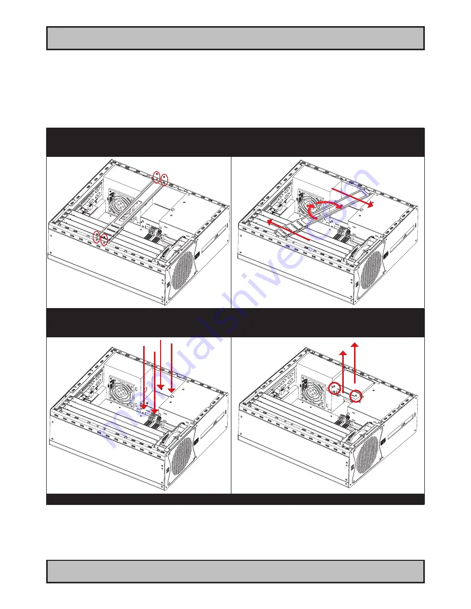
Hard Drive (HDD) removal / replacement

Note: Areas of interest are marked in this section with circles and arrows in 

RED

 color. Please disconnect ALL

cables from the computer unit and HDD’s before proceeding! 

Note: Illustration shows AC model. For DC models, the power supply must also be removed in order to gain easy access to the HDD. As of June 
2011, DC illustration is pending for this page. Meanwhile, please visit http://www.hatteland-display.com/support for assistance if needed.

1: Unscrew 4 screws on each side of the PCI bracket.

Turn anti-clockwise using a Pozidriv #2 screwdriver.

2: Push each side of the bracket, one forward and one 

backwards in a 45 degree rotation clockwise to slide it out 

of the tracks. Then lift up the the bracket to remove it.

3: Unscrew 4 screws on each side holding the HDD 

bracket at the bottom of the cabinet.

4: Lift the HDD bracket up and dismount the HDD from 

the bracket itself by unscrewing its 4 screws (2 on each 

side). Turn anti-clockwise using a Pozidriv #2 screwdriver.

Repeat the procedure backwards to finalize operation.

Summary of Contents for HT C01 Series

Page 1: ...rd or custom y operating system zzzz configuration dependent U S E R M A N U A L HT C01 Compact Computer Hatteland Display AS Åmsosen N 5578 Nedre Vats Norway Tel 47 4814 2200 mail hatteland display com www hatteland display com Please visit www hatteland display com for the latest electronic version of this manual ...

Page 2: ...hted to the respective owners The products may not be copied or duplicated in any way This documentation contains proprietary information that is not to be disclosed to persons outside the user s company without prior written consent of Hatteland Display AS The copyright notice appearing above is included to provide statutory protection in the event of unauthorized or unintentional public disclosu...

Page 3: ...g DC power input housing connector 14 Ferrites 15 Computer Upgrade Precaution Note 16 Cabinet cover removal 17 PCI Card removal replacement Introduction 18 PCI Card removal replacement Full Lenght Full Height 18 PCI Card removal replacement Half Lenght Full Height 19 PCI Card removal replacement Half Lenght Half Height 19 Hard Drive HDD removal replacement 20 DVD CD Drive removal replacement 21 Ai...

Page 4: ...ings 33 AC Model 34 DC Model 35 Technical Drawings Accessories 37 Technical Drawings 19 Rack Kit 4U 38 Technical Drawings Mounting Brackets 40 Appendixes 41 Pin Assignments Common Connectors 42 Trouble shooting 44 Declaration of Conformity 45 Return Of Goods Information 46 Terms 47 Revision History 50 ...

Page 5: ...ts incl screws for console mounting DVI 4 1 pcs of DVI I RGB VGA adapter DVI I 29P Male to DSUB 15P Female Test Reports papers 1 pcs of Product Declaration 1 pcs of Computer Checklist 1 pcs of BurnInTest Certificate For computers that include 3rd party hardware the package accessories box may also include additional CD HW Information from 3rd party supplier s This product is shipped with Contents ...

Page 6: ...6 INB100042 2 Rev 14 This page left intentionally blank ...

Page 7: ...7 INB100042 2 Rev 14 General ...

Page 8: ...twork hatteland display com You will find our website full of useful information to help you make an informed choice as to the right product for your needs You will find detailed product descriptions and specifications for the entire range on offer be it Series 1 Series 2 Computers Panel Computers Military solutions as well as the range of supporting accessories The site carries a wealth of inform...

Page 9: ...st use of emerging computer technology so you can be sure that your Hatteland Display computer offers the power needed to run modern applications with the flexibility to be installed wherever you want for any marine use Designed to perform in harsh environments Winner of Red Dot awards 2009 2007 In 2009 the Hatteland Display HT C01 standalone computer won a prestigous Red Dot Award with Honourable...

Page 10: ...10 IND100077 81 INB100042 2 Rev 14 General Exploded View Basic Construction General illustration ...

Page 11: ...evision AA XXX AAA AXXX XXXXXX NOMENCLATURE A Letters X Numbers HT C01 STD A111 000005 Example Serial Number Due to revisions numbers may be 1 to 7 digits Configuration ID for components like memory storage etc Power Input ID A 90 264VAC D 24VDC Installed Operating System ID No Installed OS ID Abbreviation for Standard STD or reserved customer ID Chassis Revision ID Electronics Mainboard Technolog...

Page 12: ...ystem Serial Number Label Placement internal Please review the General Installation Recommendations chapter in this manual before proceeding Unscrew the 3 chassis screws FIG 1 and slide the cover slightly 5mm 0 20 FIG 2 and lift the cover to reveal the label FIG 3 FIG1 FIG2 FIG3 ...

Page 13: ...13 INB100042 2 Rev 14 Installation ...

Page 14: ...mponents of all Electronics Units generally decreases with increasing ambient temperature it is therefore advisable to install such units in air conditioned rooms If there are no such facilities these rooms must at least be dry adequately ventilated and kept at a suitable temperature in order to prevent the formation of condensation inside the unit 2 With most Electronic Units cooling takes place ...

Page 15: ...he ferrites are part of the contents of the package also specified in the Contents Of Package chapter early in this manual The ferrites must be mounted on specific cables to fully comply with the Type Approvals The ferrites should be mounted clipped in place on the cable as shown in illustration as close as possible to the cable connector on the rear side of the computer product Open up the ferrit...

Page 16: ...d ground himself by using a wrist band 2 The wrist band should be connected to ground via a ground cord 3 A one megaohm resistor installed in the wrist connection end of the ground cord is a safety requirement 4 Alternatively an Static dissipative ESD work mat could be positioned at the workplace The 3M 8501 Portable Field Service Kit is a good choice for this purpose All assisting persons who mig...

Page 17: ...arrows in RED color Please disconnect ALL cables from the computer unit before proceeding 1 Unscrew 3 screws in rear of cabinet Turn anti clockwise using your fingers 2 Push cover gently down while pushing forward approx 5mm 0 20 away from the front and then lift the cover 3 Lift the cover up with both hands Repeat the procedure backwards to finalize operation ...

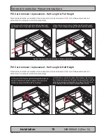
Page 18: ...ion clockwise to slide it out of the tracks Then lift up the the bracket to remove it PCI Card removal replacement Full Lenght Full Height Note Areas of interest are marked in this section with circles and arrows in RED color Please disconnect ALL cables from the computer unit before proceeding 1 Unscrew 1 screw to loosen the PCI card bracket from the cabinet Turn anti clockwise using a Pozidriv 2...

Page 19: ... clockwise using a Pozidriv 2 screwdriver Repeat the procedure backwards to finalize operation PCI Card removal replacement Half Lenght Half Height Note Areas of interest are marked in this section with circles and arrows in RED color Please disconnect ALL cables from the computer unit before proceeding 1 Place the PCI Half Length Half Height bracket as shown and fasten it with 2 screws on the top...

Page 20: ... page Meanwhile please visit http www hatteland display com support for assistance if needed 1 Unscrew 4 screws on each side of the PCI bracket Turn anti clockwise using a Pozidriv 2 screwdriver 2 Push each side of the bracket one forward and one backwards in a 45 degree rotation clockwise to slide it out of the tracks Then lift up the the bracket to remove it 3 Unscrew 4 screws on each side holdi...

Page 21: ...1 screw on the DVD CD bracket Turn anti clockwise using your fingers 2 Gently pull out the DVD CD bracket away Remember it s orientation and placement 3 Unscrew 1 screw on the back of the DVD CD drive Turn anti clockwise using fingers 4 Gently push with your fingers on the back of the DVD CD drive while using your other hand to pull it out 5 Unscrew 2 screws on the right side of the DVD CD drive T...

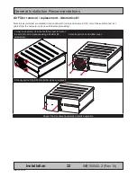
Page 22: ...th circles and arrows in RED color Please disconnect ALL cables from the computer unit and cards before proceeding 1 Unscrew 4 screws from the fan filter cover in front of the unit Turn anti clockwise using a Pozidriv 2 screwdriver 2 Gently pull out the fan filter cover 3 Gently pull out the Air Filter Either clean or replace it Repeat the procedure backwards to finalize operation ...

Page 23: ...es from the computer unit and cards before proceeding 1 Remove cabinet cover see beginning of this chapter When cabinet cover is off unscrew 1 screw on top which keeps the Air Filter Bracket in place Turn anti clockwise using a Pozidriv 2 screwdriver 2 Gently pull slide out the Air Filter Bracket 3 Gently pull out the Air Filter away from the Air Filter Bracket Either clean or replace it Repeat th...

Page 24: ...hen cabinet cover is off unscrew 4 screws from the fan filter cover in front of the unit Turn anti clockwise using a Pozidriv 2 screwdriver 2 Gently pull out the fan filter cover 3 Unscrew 1 screw on top that keeps the Air Filter Bracket in place Turn anti clockwise using a Pozidriv 2 screwdriver 4 Gently pull up the Air Filter Bracket 5 Unscrew 4 screws that keeps the fan in place Turn anti clock...

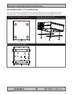
Page 25: ...ting brackets and screws for console mounting in the package Please review specifications and Technical Drawings Accessories chapter in this user manual for additional information 1 Bottom view showing 4 mounting holes 2 Mount the brackets with 4 x M6x8 Note Other longer screws may damage the computer Connector Side 3 Bottom view with mounted brackets ...

Page 26: ...r and final solution note that there is no 4U top cover 2 Showing mounting and screw included positions A 4 Panhead M6 x 8 mounted from under B 4 Countersunk M4 x8 4 on each side Sliding Rails Note The 19 inch Rack Kit 4U can also be mounted with sliding rails 20 or 26 Please review 3rd party mounting instructions found in the Sliding Rails package 1 The 3rd party sliding rails shown below The 4U ...

Page 27: ... press down this button and hold it for 3 seconds The operating system may require additionally tasks to be performed before computer shuts down and turns off the unit Reset Button Hard Reset To reset the computer in case of severe software failure press this button This reset button is a hard reset which means the operating system will NOT be warned Using this reset method may damage files and or...

Page 28: ...pecifications for your unit COM1 2 Serial Port INPUT OUTPUT Supports RS 232 using D SUB 9P Male connectors Fasten the cable to the connector using the provided screws on the cable housing itself USB7 8 and USB9 10 INPUT OUTPUT Supports any USB1 1 12Mbps or USB2 0 480Mbps compliant peripherals Drivers for most USB devices are usually included in operating system or on separate installation CD s del...

Page 29: ...connector can be configured as RGB OUT with the provided DVI 4 adapter However the signal outputted is a direct clone of RGB OUT signal For true independent output please connect a RGB cable to RGB OUT and a DVI cable to DVI I OUT without DVI 4 adapter to achieve two different desktop outputs to two different displays or monitors USB3 4 5 6 INPUT OUTPUT Supports any USB1 1 12Mbps or USB2 0 480Mbps...

Page 30: ...Full Length Profile card in one available slot Cards is normally installed from factory Please review the General Installation Recommendations chapter in this manual for more information Additionally consult the 3rd party manual available on the attached documentation CD delivered with this unit PCI Rev2 3 Slots Supports Full Height and Full Length Profile card in two available slots Cards is norm...

Page 31: ...31 INB100042 2 Rev 14 Specifications ...

Page 32: ...9 OPT A1 1 x Mounting Bracket PCI Kit HT C01 HT 00223 OPT A1 1 x 4U 19 Rack Case Kit compatible with HT 00224 00225 HT 00226 OPT A1 2 x Mounting Bracket 4mm SECC Zinc Plating RAL9011 HT 00253 OPT A1 4 x COM isolated incl cable moxa RS232 422 485 8GB Dual Channel DDR2 800 667 SDRAM 240 pin DIMM memory HT 00252 OPT A1 8 x COM isolated incl cable moxa RS232 422 485 External Connector Type T E C H N I...

Page 33: ...33 INB100042 2 Rev 14 Technical Drawings ...

Page 34: ... in any way against the interest of Hatteland Display AS Any authorized reproduction in whole or in part must include this legend Hatteland Display Proprietary information Not to be distributed to any third party without written permission Dimensions might be shown with or without decimals and indicated as mm inches Tolerance on drawings is 1mm For accurate measurements check relevant DWG file ...

Page 35: ...Technical Drawings HT C01 35 INB100042 2 Rev 14 IND100132 149 DC Model ...

Page 36: ...36 INB100036 3 Rev 4 This page left intentionally blank ...

Page 37: ...37 INB100042 2 Rev 14 Technical Drawings Accessories ...

Page 38: ...f Hatteland Display AS Any authorized reproduction in whole or in part must include this legend Hatteland Display Proprietary information Not to be distributed to any third party without written permission Dimensions might be shown with or without decimals and indicated as mm inches Tolerance on drawings is 1mm For accurate measurements check relevant DWG file Technical Drawings 19 Rack Kit 4U ...

Page 39: ... in any way against the interest of Hatteland Display AS Any authorized reproduction in whole or in part must include this legend Hatteland Display Proprietary information Not to be distributed to any third party without written permission Dimensions might be shown with or without decimals and indicated as mm inches Tolerance on drawings is 1mm For accurate measurements check relevant DWG file ...

Page 40: ...Hatteland Display AS Any authorized reproduction in whole or in part must include this legend Hatteland Display Proprietary information Not to be distributed to any third party without written permission Dimensions might be shown with or without decimals and indicated as mm inches Tolerance on drawings is 1mm For accurate measurements check relevant DWG file Technical Drawings Mounting Brackets ...

Page 41: ...41 INB100042 2 Rev 14 Appendixes ...

Page 42: ...ors used Connectors are seen from users Point Of View POV Pin Assignments 15P HD RGB VGA Pin 01 Red analog Pin 02 Green analog Pin 03 Blue analog Pin 04 Reserved for monitor ID bit 2 grounded Pin 05 Digital ground Pin 06 Analog ground red Pin 07 Analog ground green Pin 08 Analog ground blue Pin 09 5V power supply for DDC optional Pin 10 Digital ground Pin 11 Reserved for monitor ID bit 0 grounded ...

Page 43: ... 24P DVI D DVI I Pin 01 T M D S Data2 Digital RED link 1 Pin 02 T M D S Data2 Digital RED link 1 Pin 03 T M D S Data2 4 Shield Pin 04 T M D S Data4 Digital GREEN link 2 Pin 05 T M D S Data4 Digital GREEN link 2 Pin 06 DDC Clock Pin 07 DDC Data Pin 08 Analog Vertical Sync DVI I only Pin 09 T M D S Data1 Digital GREEN link 1 Pin 10 T M D S Data1 Digital GREEN link 1 Pin 11 T M D S Data1 3 Shield Pin...

Page 44: ...red units with HDD SDD hardware installed This image is not accessible from any operating system only by the Recovery Kit USB Flash provided by Hatteland Display Note that all files created after first time factory boot will be DELETED Restore from external USB recovery image HT 00215 OPT A1 1 Insert the USB Flash media into the computer usb connector 2 Restart the computer 3 On the first screen t...

Page 45: ...D HD MMD HM MMD HT MMC product ranges is in conformity with the following standards in accordance with the EMC Directive Low Voltage Directive 2006 95 EC EN 60950 EMC Directive 2004 108 EC EN 55022 Class A EN 55024 Signature Frode Grindheim Vice President Product Management Nedre Vats Norway CE MARK FIRST AFFIXED DATE 11 March 2010 Signature Arne Kristiansen Site Manager Test Commission Division O...

Page 46: ...tal credit for returned product You will either be charged separately or the amount is withdrawn from the credit If you decide to ship the missing items on the after hand you will get 100 credit for that particular invoice or items received at manufacturer incoming goods control Please contact our service sales department if additional questions Approved packaging methods materials Applies to all ...

Page 47: ... information from our suppliers We disclaim any responsibility for the consequences of any delay or cancellation from our suppliers Belated delivery gives not solely the right for cancellation 7 DELIVERY POINT OF TIME Goods are considered delivered to customer when handed over to charterer 8 FREIGHT PACKING FORWARDING FEE Hatteland Display AS charge NOK 50 in forwarding fee for orders below NOK 10...

Page 48: ... 16 RE EXPORT Goods delivered from seller may be subject to special rules of exportation in their supplier s native country Buyer is responsible to obtain necessary permissions for further export re sale 17 QUESTION IN DISPUTE To settle any dispute the Karmsund Herredsrett is approved the legal venue 1 CONTROL Control the goods immediately by receipt Examine the quantity towards the invoice packin...

Page 49: ...49 IND100077 24 INB100042 2 Rev 14 Appendix Notes ...

Page 50: ...19 Nov 2009 Revised contents of package 3rd party hardware box text page 4 Revised specifications HDD 120GB 250GB remove A356 page 32 9 AK SE 03 Dec 2009 Added Nippon and BV Type Approved page 32 10 AK SE 21 Jan 2010 Added DNV Type Approved page 32 11 JE SE 02 Sep 2010 Added info regarding DC Dxxx models page 1 5 11 14 28 32 34 Added GL Type Approval page 32 Added LRS Type Approval pending page 32...

Page 51: ...51 INB100024 2 Rev 9 This page left intentionally blank ...

Page 52: ...www hatteland display com ...

Reviews: