background image

14 


D02

B17

D08

D04

A15


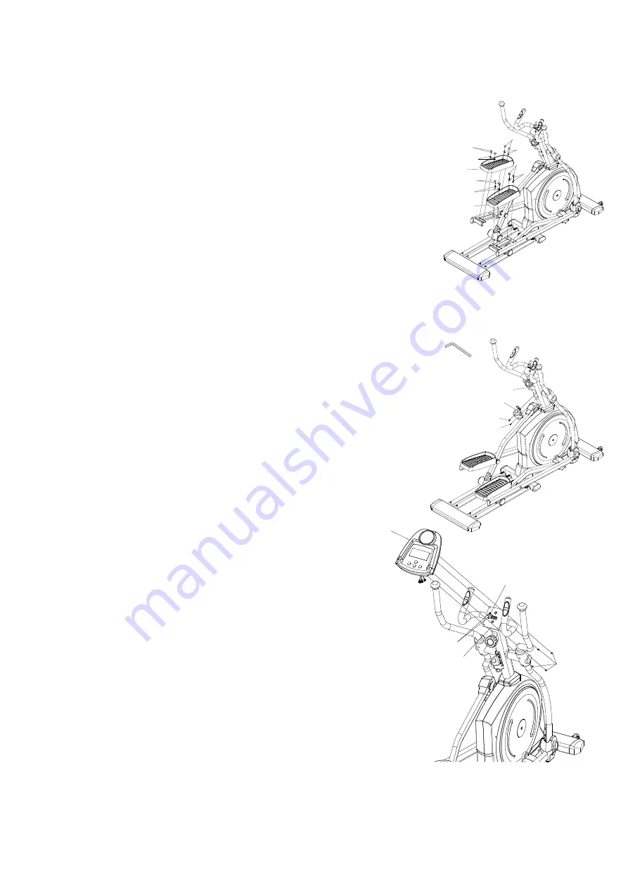
Step11. Foot Pedal & Pedal Plug Installation 

1.)  Use  8  Bolts  M6x15mm(B23)  to  assemble  the  Left  and  Right  Foot 

Pedal(C12). 

2.) Attach the 8 Foot Pedal Plugs(C34) onto the Foot Pedal(C12). 


[Tighten bolts with the Hex Tool with Phillips Screwdriver provided.] 


Step12. Bottle Holder Installation 

1.) Remove 2 Bolts (B15) from the Front Post (A02). 

2.) Attach the Bottle Holder (C27) onto the Front Post (A02) with 2 Bolts 

(B15) that were removed. 


[Remove/Tighten bolts with the M4 Allen Wrench provided.] 


Step13. ComputerInstallation 

1.) Remove 4 Screws (B17) from the back of the Computer 

(D02). 

2.) Connect the Sensor Cable (D04), Hand Pulse Sensor Wire 

(D08) to the wires that comefrom the Computer (D02) 

and then attach the Computer (D02) onto the top end of 

the Hand Pulse Handlebar(A15) with 4 Screws (B17) that 

were removed. 


[Remove/Tighten bolts with the Hex Tool with Phillips Screwdriver provided.] 

C27

B15

B15

Tool:

Allen Wrench (M4)

A02

C12

C12

B23

B23

B23

B23

C34

C34

C34

C34

Summary of Contents for KP-1000

Page 1: ...KP 1000 ELLIPTICAL BIKE USER MANUAL...

Page 2: ...1 CONTENT PRODUCT SAFETY 2 HARDWARE TOOLS 3 BOX CONTENTS 4 ASSEMBLY 6 TROUBLESHOOTING MAINTENANCE 15 WARM UP 16 PART LIST 17 EXPLODED VIEW 19...

Page 3: ...the handlebars first and make sure the pedal at your side is at its lowest position Step on the pedal and stride over the main frame then step on the other pedal When using please hold onto the handl...

Page 4: ...M8x50mm 4pcs B29 3 Nylon Nut M8 4pcs B30 4 Curve Washer M8x20x1 5t 4pcs B40 10 Bolt M8x25mm 2pcs 6 Hex Tool With Phillips Screwdriver 13mm 14mm 1pc 7 Allen Wrench M4 1pc 8 Allen Wrench M5 1pc Hardwar...

Page 5: ...PC C12 Foot Pedal 2PCS BOX CONTENTS A03 Left Dual Action Arm Set 1SET A04 Right Dual Action Arm Set 1SET Water Bottle 1PC A BOX CONTENTS A01 A07 A08 A13 A14 A02 A15 D02 C12 A03 A04 A01 Main Body 1PC A...

Page 6: ...35 Pivot Cap For Crank Link Tube 2PCS C34 Foot Pedal Plug 8PCS Lubricant 1PC BOX CONTENTS Lubricant B BOX CONTENTS A12 A05 A06 C27 C17 C18 C11 C07 C08 C28 C29 C32 C33 C30 C31 C35 C34 A12 Guide Rail 1P...

Page 7: ...ail A12 Remove Tighten bolts with the M5 Allen Wrench provided Step2 Adjusting the Adjustable Leveler 1 Turn the Adjustable Levelers C05 on the MainBody A01 and Guide Rail A12 as needed to level the e...

Page 8: ...Brush tool isrecommended Step5 Left and Right Foot Pedal Linkbar Installation 1 Remove the tape from the joint of the Right Dual Action Arm Set A04 2 Insert the Right Dual Action Arm Set A04 all the w...

Page 9: ...et A08 secure the Right FootBar Set A06 in position with 1 Bolt M8x16mm B32 and 1 Washer 5 16 x20x2 0t B33 Tighten bolt with the Hex Tool with Phillips Screwdriver provided CAUTION Make Sure The Bushi...

Page 10: ...lon nut with the Hex Tool with Phillips Screwdriver and M5 Allen wrench provided 9 Fit one Nut Cap C11 onto M8x16mm Hexagon Head Bolts B32 of the Right Rotate Bar A08 Repeat above steps to install the...

Page 11: ...A07 C23 B41 B33 B32 C11 B32 B33 B41 C11 B32 B33 B41 C23 A08 B41 B33 B32 A04 A06 B24 B33 B29 B32 B33 B41 A02 A05 A03 B32 B33 B41 C25 E02 E02 C25 C24 C24 B31 C22 C22 B41 B41 B24 B29 B33 C20 F01 C20 A11...

Page 12: ...over for Crank Link C35 to the pivot of Right Left Wheel Bar Set A08 A07 and Crank A11 using 4 Screws M5x16mm B21 3 Assemble two sets of Wheel Caps C32 C33 to the wheel of the Left and Right Wheel Bar...

Page 13: ...and Bar Post to the Front Post A02 Tighten bolts with the M5 Allen Wrench provided Step8 Right Left Handrails Installation 1 Slide the Left and Right Handrails A13 A14 into the Dual Action Tube Use 4...

Page 14: ...Cover A C17 and Handrail Arm Decorative Cover B C18 onto the Right Handrail Arm A04 with 4 Screws M5x16mm B21 Tighten bolts with the Hex Tool with Phillips Screwdriver provided Step10 Left Right Fron...

Page 15: ...27 onto the Front Post A02 with 2 Bolts B15 that were removed Remove Tighten bolts with the M4 Allen Wrench provided Step13 ComputerInstallation 1 Remove 4 Screws B17 from the back of the Computer D02...

Page 16: ...tead of just one Try to maintain moderate pressure while holding onto the hand pulse sensors Make sure that the wire connections for the hand pulse sensors are secure MAINTENANCE Cleaning The elliptic...

Page 17: ...tward Pull your feet as close into your groin as possible Gently push your knees towards the floor Hold for 10 counts Toe Touches Slowly bend forward from your waist letting you back and shouldersrela...

Page 18: ...lded Guide Rails Tube 1 B31 Shaft for Dual Action Arm Pivot 2 A13 Dual Action Handlebar Left 1 B32 M8 Hex Head Screw 10 A14 Dual Action Handlebar Right 1 B33 5 16 Washer 8 A15 Welded Hand Pluse Handle...

Page 19: ...mall Crank Decorated Cover 2 C17 Pivot Cover L 2 C37 Dual Action Arm Plug 2 C18 Pivot Cover R 2 D01 Hand Pulse Sensor 1Set C19 Pulley 1 D02 Computer 1 C20 Roller 4 D03 Magnetic Flywheel 1 C21 Upright...

Page 20: ...B32 B33 B33 B33 B32 B35 E02 E02 E02 E02 E02 E02 E02 E02 E02 B22 B22 D05 D07 D05 D03 B25 B05 B19 C26 C26 C26 C26 C25 C25 C25 C25 C25 C25 C25 C25 C24 C24 C24 C24 C24 C24 C24 C24 C24 C23 C23 B16 B16 B31...

Reviews: