background image

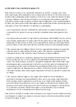
OWNERS WARRANTY RESPONSIBILITIES:

•  As the engine owner, you are responsible for the performance of the required 

maintenance listed in your owner's manual. Motorenfabrik Hatz recommends that you
retain all receipts covering maintenance on your engine, but Motorenfabrik Hatz cannot
deny warranty solely for the lack of receipts or for your failure to ensure the 
performance of all scheduled maintenance. 

•  As the engine owner, you should be aware, however, that Motorenfabrik Hatz may

deny you warranty coverage if your engine or a part has failed due to abuse, neglect,
improper maintenance or unapproved modifications.

•  You are responsible for presenting your engine to a Motorenfabrik Hatz authorized

service center as soon as a problem exists. The warranty repairs should be completed in
a reasonable amount of time, not to exceed 30 days.

If you have any questions regarding your warranty rights and responsibilities, you should
contact HATZ DIESEL OF AMERICA, Inc. at (262) 544-0254. 

HATZ DIESEL SUPPLEMENTAL WARRANTY FOR MODEL YEAR 2015 EPA
CERTIFIED ENGINES.

PARTS WITH SUPPLEMENTAL LIMITED WARRANTY

.

The following limited warranty is supplemental to the standard HATZ DIESEL LIMITED
ENGINE WARRANTY and covers Model Year 2015 EPA certified engines and applies to
the following exhaust emission-related components: 

•  Fuel injection pump

•  Injection nozzle

•  Bimetallic strip

•  Crankcase breather valve assembly

•  Air cleaner housing

•  Oil filler cap

•  Intake and exhaust gaskets at head interfaces

•  Emission Control Information Labels

46

Summary of Contents for 1B20

Page 1: ...A AR R 2 20 01 15 5 E EP PA A C CE ER RT TI IF FI IE ED D N NO ON NR RO OA AD D C CO OM MP PR RE ES SS SI IO ON N I IG GN NI IT TI IO ON N E EN NG GI IN NE ES S I IN NC CL LU UD DE ES S S SU UP PP PL LE EM ME EN NT TA AL L I IN NF FO OR RM MA AT TI IO ON N T TO O T TH HE E O OW WN NE ER R S S M MA AN NU UA AL L F FO OR R M MO OD DE EL L Y YE EA AR R 2 20 01 15 5 C CA AL LI IF FO OR RN NI IA A R RE...

Page 2: ...his Instruction Manual on to the next user or to the following engine owner Always have service work performed by qualified specialists To this effect we recommend that you consult one of the 500 HATZ service stations There your engine is repaired by staff who constantly undergo training and who use both original HATZ spare parts and HATZ tools The world wide HATZ service network is also available...

Page 3: ...Oilbath air cleaner maintenance 23 5 3 2 Changing engine oil 24 5 3 3 Checking and adjusting valve clearances 25 5 3 4 Cleaning cooling air area 27 5 3 5 Checking screw connections 27 5 3 6 Cleaning the exhaust mesh inlet 27 5 4 Maintenance every 500 operating hours 29 5 4 1 Renewing fuel filter 29 5 4 2 Air cleaner maintenance 31 5 5 Maintenance every 1000 operating hours 32 5 5 1 Cleaning the oi...

Page 4: ...ical system may cause sparking and must there fore be avoided Provide protection against contact with rotating parts once the engine is connected to the driven equipment or machine HATZ protective guards are available for the belt drive of the cooling fan and alternator drive sys tems Always observe the start up information in the operating instructions before starting the engine this is particula...

Page 5: ...wear necklaces bracelets or any other things which you could get caught with Please pay attention to all advice and warning stickers placed on the engine and keep them in legi ble condition In case a label has come off or is no longer clearly legible it must be replaced imme diately To this effect please contact the HATZ service station in your area We accept no liability for damage resulting from...

Page 6: ...arter motor 7 Voltage regulator 8 Crankshaft power take off 9 Oil drain plug 10 Speed adjustment lever 11 Oil filter 12 Engine mountings 13 Ignition key 14 LED display 15 Intake opening for cooling and combustion air 16 Oil filler pipe and dipstick 17 Recoil starter 18 Engine shutdown pin 19 Dry type air cleaner 20 Suspension lug see also Fig 42 Pos 1 21 Fuel tank cap 22 Noise insulating hood ...

Page 7: ... oil sump l approx l approx 0 9 1 2 6 1 0 9 1 1 1 1 2 8 1 1 5 1 3 2 1 1 5 1 Difference between max and min levels without oil sump with oil sump l approx l approx 0 5 1 1 6 1 0 5 1 0 5 1 1 8 1 0 8 1 2 2 1 0 8 1 Lubricating oil consumption after running in max 1 of fuel consumption at full load Lubricating oil pressure oil temperature 100 C approx 2 5 bars at 3000 r p m Direction of rotation power ...

Page 8: ...Z service center in your area Pending complete installation the engine must not be started Moreover we would like to point out that in this case commissioning of the machine is also pro hibited until it has been verified that the machine into which this engine is to be incorporated complies with all the safety precautions and reg ulations provided by law Refer also to the Declaration for Incorpora...

Page 9: ...d CARB VARIABLE SPEED ULTRA LOW SULFUR FUEL ONLY Power Category EMISSION CONTROL SYSTEM INFORM Every engine is equipped with an additional loose engine type plate If the original type plate on the engine is not readily visible after the engine is installed in the equipment then the second loose type plate must be attached on the equipment in such a manner that it is readily visible to an average p...

Page 10: ...note that the engine has a closed crankcase ventilation system Exceeding the maximum admissible tilt angle see chapter 3 1 Technical data can cause damage to the engine In cases where the maximum angle is exceeded the engine must be stopped immediately Before restarting the engine must be in a hori zontal position and the air filter and inlet mani fold must be checked for any oil contamination If ...

Page 11: ...re at which the engine is operated Inappropriate engine oil may shorten the engine s service life significantly 40 30 20 10 0 10 20 30 40 50 104 86 68 50 32 14 4 22 40 OIL SAE C F 5W 30 5W 40 10W 40 10W 30 15W 40 30 40 122 10W When adding oil or checking the oil level the engine must be horizontal 6 Remove oil filler screw and add engine oil Lubricating oil capacity see Chapter 3 1 7 To check the ...

Page 12: ...re tight 2444 5 2440 10 4 1 3 Fuel Stop the engine before refilling the fuel tank Never refuel near a naked flame or sparks which could start a fire Don t smoke Use only pure fuel and clean filling equipment Take care not to spill fuel All diesel fuels which satisfy the following speci fications are suitable EN 590 or BS 2869 A1 A2 or ASTM D 975 1D 2D Important The use of fuels of different specif...

Page 13: ...the engine in closed or badly ventilated rooms danger of poisoning Before starting the engine ensure that no one is in the danger area close to the engine or equipment and that all protective guards are fitted 4 2 1 Preparations for starting If possible disengage the engine from any driven equipment The auxiliary equipment should always be placed in neutral Recoil starter 13 Risk of injury A damag...

Page 14: ...engine speed adjusting device first to STOP position 1 Then set it to START po sition 2 Now the engine is ready for starting 16 Never use starting sprays Important After long time standstill approx 6 months or even longer or first operation operate engine with low adjusted speed and without load for approx 20 sec after start This measure assures a lubrication of all bearings before increasing spee...

Page 15: ...e engine Devices which are not securely fastened should be restrained with the foot 18 Grip the handle with both hands 19 Commence pulling the starting cable vigorous ly and at an increasing speed do not jerk it violently until the engine starts Note If after several attempts of starting the exhaust begins to emit white smoke move the speed ad justment lever to the STOP position and pull the start...

Page 16: ... key must spring back to position I and remain there during engine operation The battery charge and oil pressure lights should extinguish directly after the engine starts The display lamp 1 lights up to show that the engine is running Prior to starting up again the key has to be returned to position 0 When the engine is running the starter repeat lock in the ignition switch will prevent the starte...

Page 17: ...y at least 90 using suitable pliers The lead seal wire will break off As soon as the emergency start lever is in the starting position the electric starter or recoil starter can be used Chapter 4 2 2 The oil level must always be checked before an emergency start as insufficient oil pressure can lead to complete damage of the engine within a very short time After this the engine can only be stopped...

Page 18: ...error memory This model has no specific characteristic which appears externally If the engine stops immedi ately after starting this indicates a reaction of a monitoring element of the automatic shut off feature Before performing further starting at tempts locate and eliminate the malfunction Chapter 6 2 Even with automatic shutdown monitoring the oil level must be checked every 8 15 operat ing ho...

Page 19: ...to its initial position Depending upon the model the battery charge indicator 2 and oil pressure warning indicator 3 will come on again after the engine comes to a stop Fig 26 and Fig 27 Turn the key to position 0 and remove it All the indicator lights must go out Fig 26 and Fig 27 Note Failure to return the starter key to position 0 may result in the battery being totally discharged If operation ...

Page 20: ... or before each daily start up Check oil level Examine the lower section of the oilbath air cleaner to ensure correct oil level and freedom from con tamination change the oil if it contains sludge On version with cyclone type dust trap empty the dust collector Check combustion and cooling air intake zone Check air cleaner maintenance indicator Check the water trap 5 2 1 4 1 2 5 3 1 5 3 1 5 2 2 5 2...

Page 21: ... oil Chapter 5 3 2 Check valve clearances and adjust if necessary Chapter 5 3 3 Examine screw connections chapter 5 3 5 Do not tighten the cylinder head fastening If the engine is not used frequently change the engine oil after 12 months at the latest regard less of the actual number of hours it has been in operation 20 0000 052 502 02 1h max OIL 500h 250h IN EX max AUTOM Model without automatic v...

Page 22: ...engine is operated while the oil level is below the min mark or above the max mark it can cause damage to the engine 5 2 2 Check air intake area for combustion and cooling Heavy contamination is an indication that in creased dust accumulation necessitates a corre spondingly shorter maintenance interval Chapter 5 3 1 5 3 4 and 5 4 2 30 Check air intake points for severe blockage due to leaves heavy...

Page 23: ...lows several times per day 1 2440 13 5 2 4 Checking the water trap The intervals at which you should check the water trap depend entirely on the amount of water in the fuel and the care taken when re fuelling The normal interval is once a week 34 Loosen hexagon screw 1 with approx 3 4 rotations Trap the drops which emerge in a transparent vessel Since water has a greater specific grav ity than die...

Page 24: ...cleaner maintenance 36 Trap the old oil and dispose of it in accordance with local legislation Take off the oil tank 1 Remove contaminated oil and sludge from the oil tank and clean it out Rinse out filter element 2 in diesel oil allow it to drip thoroughly and wipe it down before re assembling the air cleaner If severely contaminated clean filter housing 3 Never attempt to repair the oilbath air ...

Page 25: ...nut 5 3 2 Changing engine oil The engine must be standing level and be switched off Only change the oil when the engine is warm Danger of scalding from hot oil Trap the old oil and dispose of it in accordance with local legislation 2440 13 38 39 Take out oil drain plug 1 and allow the oil to drain out Fig 38 without oil sump Fig 39 with oil sump Clean the oil drain plug 1 fit a new washer 2 insert...

Page 26: ... carry out adjustments when the engine is cold 10 30 C 40 Remove cover to air filter 41 Remove noise insulating hood 2443 12 Version with oilbath air cleaner 42 On version with oilbath air cleaner remove screw 2 and take off cover plate with noise insulating hood Model for rammer operation 1B20 R Remove cover of air cleaner Fig 40 43 After having removed the screws and nuts re move the noise insul...

Page 27: ...in the normal direction of rotation and align exactly to the OT marking 46 Check valve clearances with feeler gauge 1 For the setting refer to Chapter 3 1 If valve clearances require adjusting slacken off screw 2 and turn hex nut 3 until feeler gauge 1 can be pulled through with just slight resistance when screw 2 is retight ened Fit cover for cylinder head and tighten evenly always using a new ga...

Page 28: ...e up slack if necessary provided that these can be reached during maintenance work Do not tighten the cylinder head bolts 47 The adjusting screws at the engine governor and on the injection system are sealed with lacquer and are not to be tight ened or adjusted 5 3 6 Cleaning the exhaust mesh inlet Exhaust system components will natu rally be hot and must not be touched while the engine is running...

Page 29: ...el for rammer operation 1B20 R In addition to the maintenance work described above the model for rammer operation requires that the inlet of the crankcase ventilation into the exhaust manifold is checked for free passage 51 Remove the hose from the manifold 52 Check the pipe socket for free passage Elimi nate deposited matter using a screwdriver or a similar tool Subsequently remount the hose 53 S...

Page 30: ...not smoke Important Keep the entire area clean so that no dirt reaches the fuel Fuel particles may damage the injection system Model with double fuel filter system 55 This system consists of a maintenance free external filter 1 Fig 55 and a replaceable cartridge filter which is installed in the tank Fig 56 The advantage of this system consists in retaining dirt particles which might get into the f...

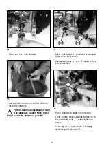
Page 31: ...uel injection system takes place automatically 2441 8 Model with external fuel filter no fuel filter in the tank Empty the fuel tank by taking out screw 1 Fig 34 or Fig 35 and allow the fuel to drain into a clean vessel This fuel can be re used later 58 Unscrew the fuel filter from its mount Place a suitable vessel under the filter to trap the residual fuel 59 Pull off fuel supply line 1 at both e...

Page 32: ...eed Chap 5 2 3 However the filter cartridge should always be re placed after 500 operating hours at the latest 60 Remove the air cleaner cover 2443 12 61 Unscrew and remove knurled nut 1 and take off air cleaner element 2 Clean the filter compartment and the cover Dirt and other foreign bodies must not be allowed to enter the engine s air inlet points 62 On versions with a mechanical air cleaner s...

Page 33: ...r cracks or any other type of damage to the paper filter by holding it inclined towards the light or by shining a light source through it Important The slightest damage to the paper filter rules out it being used any longer Re assemble the filter cartridge in the reverse order of work 2444 10 5 5 Maintenance every 1000 operating hours 5 5 1 Cleaning the oil filter The oil filter should be cleaned ...

Page 34: ...o animals persons or yourself 2445 10 67 Check joint washer 1 whether it is damaged replacement if necessary Coat packing rings 1 and 2 slightly with oil before assembly 68 Put in oil filter and press until limit stop Check whether tension springs sit close to oil filter with both ends 1 before tightening screw Check the oil level and restore to the max level if required Chapter 4 1 1 33 ...

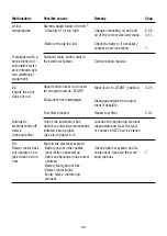
Page 35: ... inadequate resistance to low temperatures Move lever to START position Move to operating position by pulling the pin gently Add fuel Systematically check the entire fuel supply system If still no fault found check engine feed line check fuel filter Check valve clearances adjust if necessary See workshop manual See workshop manual Operate preheater optional extra Disengage engine from equip ment i...

Page 36: ...ked One of the automatic shut down s monitoring elements has initiated a stop signal See also Chapter 6 4 Fault in the electrical system Battery and or other cables incorrectly connected up Cable connections loose and or oxidised Battery faulty and or flat Starter motor faulty Faulty relays monitoring element Change lubricating oil and add oil of the correct viscosity class Check the battery if ne...

Page 37: ...alve clearances incorrect Injector not functioning Add fuel Change fuel filter Ensure adequte tank venting Check fuel system for penetration of air Check air vent valve Contact a HATZ service station Localise the monitoring element responsible and clear the fault or contact a HATZ service station Check oil lubrication Check air cooling zone for con tamination See workshop manual Check electrical e...

Page 38: ...n engine Inadequate cooling Contamination of entire cooling air zone Air duct panels not properly sealed Operation off load for a prolonged period Drain off lubricating oil as far as upper mark on dipstick Clean cooling air zone Check cooling air deflector plates and shafts for complete ness and airtight seal Operate the machine at about 70 load until moisture no longer emerges from the ex haust 5...

Page 39: ... case of an emergency start in manual mode leave the battery which might be dis charged connected to the engine Before starting emergency operation without battery proceed as follows before starting disconnect plug connection to voltage regulator for engine models with mounted instrument box picture 26 Turn key to off position 0 and remove disconnect plug connection to instrument box for engine mo...

Page 40: ...39 ...

Page 41: ......

Page 42: ...TAL INFORMATION TO THE OWNER S MANUAL FOR MODEL YEAR 2015 EPA CERTIFIED NONROAD COMPRESSION IGNITION ENGINES EPA EMISSION CONTROL SUPPLEMENTAL WARRANTY STATEMENT AND EMISSION RELATED INSTALLATION INSTRUCTIONS 41 ...

Page 43: ... parts and engine operating conditions Maintenance instructions for EPA related engine parts Emission control system and adjustments Warranty statement Emission related installation instructions ENGINE PARTS AND OR EQUIPMENT RELATED TO EPA EXHAUST EMISSION REGULATIONS Parts which are mandatory for engine operation The following parts as manufactured according to HATZ specifications are mandatory f...

Page 44: ...t HATZ authorized Service Center for necessary repairs The engine is designed and adjusted to operate most efficiently at the following conditions Air temperature of 25 C 77 F Atmospheric pressure of 100 kPa 14 5 psi Relative humidity of 30 Operation of the engine at conditions other than above will affect performance and exhaust emissions Normally the equipment manufacturer takes this into accoun...

Page 45: ...he exhaust quality of the engines can be influenced by the execution the quality of execution of above described maintenance work Therefore the maintenance work has to be carried out by a qualified workshop Hatz authorised workshops for example are qualified workshops Hatz Diesel of America will give you respective addresses if required EMISSION CONTROL SYSTEM AND ADJUSTMENTS The emission control ...

Page 46: ...reather valve assembly Air cleaner housing Oil filler cap Intake and exhaust gaskets at head interfaces Emission Control Information Labels Where a warrantable condition exists Motorenfabrik Hatz will repair your engine at no cost to you including diagnosis parts and labor MANUFACTURERS WARRANTY COVERAGE The Model Year 2015 EPA certified nonroad compression ignition engines are warranted for 1500 ...

Page 47: ...ne to a Motorenfabrik Hatz authorized service center as soon as a problem exists The warranty repairs should be completed in a reasonable amount of time not to exceed 30 days If you have any questions regarding your warranty rights and responsibilities you should contact HATZ DIESEL OF AMERICA Inc at 262 544 0254 HATZ DIESEL SUPPLEMENTAL WARRANTY FOR MODEL YEAR 2015 EPA CERTIFIED ENGINES PARTS WIT...

Page 48: ...rts This warranty is transferrable to subsequent owners only under the named warranty coverage conditions In order to obtain service under this warranty the retail purchaser should contact Hatz Diesel of America Inc at 262 544 0254 for information and the nearest service center The retail purchaser will not be charged for diagnostic labor which leads to the determination that a warranted part is d...

Page 49: ...enance you must place duplicate labels on the equipment EQUIPMENT LABELLING REQUIREMENTS FUEL LABEL Chapter 3 5 The fuel label has to be permanently attached to the equipment In case of an engine mounted fuel tank every engine is equipped with an additional fuel label nearby the fuel inlet Otherwise there are two loose fuel labels available with the engine If the original fuel label is not readily...

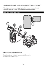
Page 50: ... properly install the exhaust system and related components consistent with the EPA emission regulation requirements Exhaust silencers and protection guard The exhaust silencer is fitted in connection with flat washers Fixation is done by Allen screws 1 3 4 4 2 49 1B20 1B27 1B30 1B40 1B50 ...

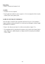
Page 51: ...engine is installed in the equipment and placed in service the sampling of exhaust emissions can be performed in a way that prevents diluting the exhaust sample with ambient air as follows Remove the exhaust mesh insert if so fitted as described in chapter 5 3 6 The sampling probe for measuring the emissions can be put into the exhaust silencer outlet There are no additional pipes or clamps needed...

Page 52: ...NTAL INFORMATION TO THE OWNER S MANUAL FOR MODEL YEAR 2015 CALIFORNIA REGULATIONS FOR HEAVY DUTY OFF ROAD ENGINES CALIFORNIA EMISSION CONTROL WARRANTY STATEMENT AND EMISSION RELATED INSTALLATION INSTRUCTIONS 51 ...

Page 53: ... Maintenance instructions for CARB related engine parts Emission control system and adjustments Warranty statement Emission related installation instructions ENGINE PARTS AND OR EQUIPMENT RELATED TO CARB EXHAUST EMISSION REGULATIONS Parts which are mandatory for engine operation The following parts as manufactured according to HATZ specifications are mandatory for engine operation which meets CARB...

Page 54: ...authorized Service Center for necessary repairs The engine is designed and adjusted to operate most efficiently at the following conditions Air temperature of 25 C 77 F Atmospheric pressure of 100 kPa 14 5 psi Relative humidity of 30 Operation of the engine at conditions other than above will affect performance and exhaust emissions Normally the equipment manufacturer takes this into account durin...

Page 55: ...djustments are needed or possible CALIFORNIA EMISSION CONTROL SYSTEM WARRANTY STATEMENT YOUR WARRANTY RIGHTS AND OBLIGATIONS The California Air Resources Board and Motorenfabrik Hatz GmbH Co KG are pleased to explain the emission control system warranty on your Model Year 2015 engine In California new heavy duty off road engines must be designed built and equipped to meet the State s stringent ant...

Page 56: ...f all scheduled maintenance As the heavy duty off road engine owner you should however be aware that Motorenfabrik Hatz GmbH Co KG may deny you warranty coverage if your heavy duty off road engine or a part has failed due to abuse neglect improper maintenance or unapproved modifications Your engine is designed to operate on low sulfur diesel fuel or ultra low sulfur diesel fuel only Use of any oth...

Page 57: ...15 California certified Heavy Duty off road engines and applies to the following exhaust emission related components Fuel injector Fuel injection pump Bimetallic Strip Intake manifold Exhaust manifold Crankcase breather valve Oil filler Cap Intake and exhaust gaskets at head interfaces Oil pressure switch Electric starter with wiring harnesses optional Sealing gaskets for exhaust muffler Sealing g...

Page 58: ...warranty is transferrable to sub sequent owners within the original twenty four 24 months time period In order to obtain service under this warranty the retail purchaser should contact Hatz Diesel of America Inc at 262 544 0254 for information and the nearest service center The retail purchaser will not be charged for diagnostic labor which leads to the determination that a warranted part is defec...

Page 59: ...enance you must place duplicate labels on the equipment EQUIPMENT LABELLING REQUIREMENTS FUEL LABEL Chapter 3 5 The fuel label has to be permanently attached to the equipment In case of an engine mounted fuel tank every engine is equipped with an additional fuel label nearby the fuel inlet Otherwise there are two loose fuel labels available with the engine If the original fuel label is not readily...

Page 60: ... properly install the exhaust system and related components consistent with the EPA emission regulation requirements Exhaust silencers and protection guard The exhaust silencer is fitted in connection with flat washers Fixation is done by Allen screws 1 3 4 4 2 59 1B20 1B27 1B30 1B40 1B50 ...

Page 61: ...engine is installed in the equipment and placed in service the sampling of exhaust emissions can be performed in a way that prevents diluting the exhaust sample with ambient air as follows Remove the exhaust mesh insert if so fitted as described in chapter 5 3 6 The sampling probe for measuring the emissions can be put into the exhaust silencer outlet There are no additional pipes or clamps needed...

Page 62: ...CALIFORNIA Proposition 65 Warning Diesel engine exhaust and some of its constituents are known to the State of California to cause cancer birth defects and other reproductive harm ...

Page 63: ... 2 20 01 14 4 0 0 1 1 Printed in Germany USA EPA IV CARB Motorenfabrik Hatz GmbH Co KG Ernst Hatz Str 16 94099 Ruhstorf a d Rott Deutschland Tel 49 8531 319 0 Fax 49 8531 319 418 marketing hatz diesel de www hatz diesel com CREATING POWER SOLUTIONS ...

Reviews: