Page 4
BCS3000M-9
4.
Determine the burner fuel control motor type and install a jumper:
a. From fuse 5 to ground for a Honeywell M6284 or Barber-Coleman EA57 medium torque
motor.
b. From fuse 5 to fuse 7 for a Barber-Coleman EA71 or EA73 high torque motor.
5.
Verify that the
SELECT R4
jumper on the printed circuit board is in the correct position for
the burner application. Position
A
(default) holds the fuel motor at low fire during purge while
position
B
drives the fuel control motor open until purge time is completed.
6.
Wire the fuel valves, valve position limit switches and fuel pressure limit switches as shown
on the external component wiring diagram.
7.
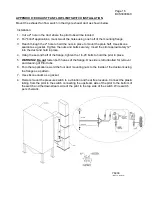
Install the exhaust fan flow limit switch in the dryer exhaust duct as shown in Appendix D.
Wire the normally open contact of the exhaust flow limit to the appropriate terminals in either
the burner junction box or the BCS control panel.
8.
Install a limit switch on the exhaust damper set to close when the damper is greater than
50% open.
9.
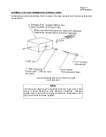
Install the stack temperature thermocouple in the dryer exhaust duct to sense exhaust gas
temperature. See Appendix E
for installation instructions.
AND / OR
10. Install a Hauck Rapid Response material temperature thermocouple in the material
discharge chute to sense the temperature of the material leaving the dryer. See Appendix F
for recommended installation.
11. Connect the thermocouples to the appropriate terminals in the BCS control panel using
thermocouple cable of the same type as the Material and/or Stack thermocouples.
12. Install the pilot and main flame scanners on the burner and wire them to the appropriate
terminals in the burner junction box. Reference burner instructions for scanner installation
details.
13. Refer to the external component wiring diagram for interconnection between the burner
junction box and the BCS panel terminal strips.
IMPORTANT
Thermocouple cables must be separated from AC power and control wiring to avoid
interference and nuisance shutdowns. Observe polarity when making thermocouple
connections. Regardless of thermocouple type, the red wire is always negative.
Shielded cable may be used to provide additional protection from AC power and
radio frequency (RF) interference.
Only one end of the cable should be
grounded.
Use a ground terminal in the BCS panel for this purpose.
IMPORTANT
The flame scanner and control motor position feedback signals should be
run in a separate cable from the burner junction box to the BCS control
panel.
This cable may be run along with thermocouple cables but must be
separated from all other AC power and control cables. Shielded cable may be
used to provide additional protection from AC power and radio frequency (RF)
interference.
Only one end of the cable shield should be grounded.
Use one
of the ground terminals in the BCS control panel for this purpose.


