background image

2    Safety 


2.1


Intended use 


Risk of explosion! 

The discharging power pack may generate sparks which ignite 

gases, dust or similar substances. 
•  Never install or use the discharging power pack in areas with 

potentially explosive atmospheres. 

 
The discharging power pack is intended exclusively for the supply of 
alternating high voltage to HAUG ionizing units with X-2000 
connector. In combination with an ionizing unit, electrostatic charges 
are neutralized in a production process. 
Always observe the installation and operating conditions indicated in 
these operating instructions. 

Warranty only covers products, accessories or spare parts of HAUG 
GmbH & Co. KG. 


Summary of Contents for 01.7908.005

Page 1: ...Static Line Operating instructions Discharging power pack EN SL SLC MT Ident number 01 7909 055 100 V 01 7909 005 115 V 01 7908 005 230 V Keep for future use GB...

Page 2: ......

Page 3: ...roduct overview 8 4 Install 9 5 Operate 13 5 1 Normal operation 13 5 2 Cyclic operation 13 6 Troubleshooting 14 6 1 Replacing fuse 15 6 2 Flow chart 16 7 Accessories spare parts 17 8 Technical data 18...

Page 4: ...eviated HV in these operating instructions e g HV terminal The illustrations in this document are a simplified representation of the product They render only the technical facts and provide support fo...

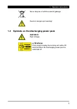
Page 5: ...ose of with household garbage Caution danger spot warning 1 2 Symbols on the discharging power pack WARNING High voltage ATTENTION Only plug in unplug the ionizing unit at the HV terminal when the dis...

Page 6: ...In the event of visible damage or suspected electrical defects take the discharging power pack out of operation immediately and secure against inadvertent reuse Protect the discharging power pack from...

Page 7: ...tmospheres The discharging power pack is intended exclusively for the supply of alternating high voltage to HAUG ionizing units with X 2000 connector In combination with an ionizing unit electrostatic...

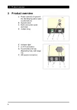
Page 8: ...er switch is lit green if the discharging power pack is switched on B Signal socket C Earth connection point terminal D Jumper plug E Indicator light F 2 x HV connection G Fuse holder with fuse Replac...

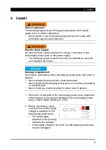
Page 9: ...ontinuous overloading of the discharging power pack may result in failures Never exceed the permissible connected length Never install the discharging power pack on a surface generating or radiating h...

Page 10: ...discharging power pack must be connected to ground potential in line with applicable standards Grounding cables of at least 1 5 mm2 must be used 5 Connect the discharging power pack to the supply volt...

Page 11: ...efore plugging in unplugging ionizing unit 6 Connect the ionizing unit to the HV terminal of the discharging power pack Insert the ionizing unit s HV plug in the HV terminal of the discharging power p...

Page 12: ...e Pin 2 0 V Pin 3 not used Pin 4 not used Pin 5 Clock switch connection Pin 6 Clock switch connection PE Shield Ground signal ground NOTE The discharging power pack only supplies voltage if the signal...

Page 13: ...eration fails the indicator light turns off In order to correct the malfunction proceed with troubleshooting the error Refer page 14 5 2 Cyclic operation The signal line K6 is connected to the K6 sign...

Page 14: ...is provided on the back of the envelope Fault Cause Troubleshooting Mains switch does not illuminate Mains failure Check mains fuse Defective fuse in discharging power pack Check fuse in discharging...

Page 15: ...red fuses Never bridge the fuse The unit type and the rated voltage are indicated on the nameplate 1 Disconnect discharging power pack from supply 2 Determine and remove the cause for the blown fuse 3...

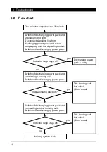
Page 16: ...g socket Switch on the discharging power pack yes Switch off discharging power pack and connecting a ionizing unit Switch on the discharging power pack This ionizing unit has a fault Short circuit Ion...

Page 17: ...e authorized local sales agent of Mettler Toledo Article Order number Point electrode 11107765 Optional second electrode 11107762 U Electrode universal 11107764 U Electrode small 11140161 Ionizing kit...

Page 18: ...3 C HV terminals 2 High voltage 6 7 1 kV Short circuit current Ik 5 mA Cannot be used in pulsed mode 8 2 Supply voltage Unit type Rated value Frequency range Power consumption 01 7909 055 100 V 10 50...

Page 19: ...e mean seal level to 2000 m Temperature Rated application range 5 to 45 C Limit range for storage and transport 15 to 60 C Relative humidity Rated application range A RF B C Air pressure Rated applica...

Page 20: ...l data 20 8 4 Housing Protection type IP 20 Protection class I Overvoltage category II Pollution severity 2 Mains connection About IEC power cord Dimensions Height 170 mm Width 110 mm Depth 100 mm Wei...

Page 21: ...ct the signalling line from the discharging power pack 5 Remove the discharging power pack from the production process 9 1 Storing Always store our products in a dry and cool place 9 2 Disposing Never...

Page 22: ......

Page 23: ......

Page 24: ...EN SL SLC MT v03gb docx V03 22 01 2019 D 0332 GB made by...

Reviews: