background image

8    Technical data 


25 


8.5


Housing 

Protection type 01.7924.000, 
01.7925.000 

IP 54 

Protection type 01.7926.000, 
01.7927.000 

IP 20 

Protection class 

Network supply line 
01.7924.000, 01.7925.000 

Approx. 2.6 m, attached to the 
device 

Network supply line 
01.7926.000, 01.7927.000 

Power supply cord 


Dimensions: 


Height 

245 mm 

Width 

128 mm 

Depth 

125 mm 


Weight: 

5 kg 


Summary of Contents for 01.7924

Page 1: ...Static Line Operating instructions Discharging power pack EN 9 Sine UL Ident number 01 7924 XXX 230 V 01 7925 XXX 115 V 01 7926 XXX 230 V 01 7927 XXX 115V Keep for future use GB...

Page 2: ......

Page 3: ...he signalling socket K1 15 5 2 1 Pulsing high voltage 15 5 2 2 Monitoring the HV 16 5 2 3 Monitoring the thermal protection 17 5 2 4 External reset 17 6 Troubleshooting 18 6 1 Replacing fuse 19 6 2 Fl...

Page 4: ...eviated HV in these operating instructions e g HV terminal The illustrations in this document are a simplified representation of the product They render only the technical facts and provide support fo...

Page 5: ...ose of with household garbage Caution danger spot warning 1 2 Symbols on the discharging power pack WARNING High voltage ATTENTION Only plug in unplug the ionizing unit at the HV terminal when the dis...

Page 6: ...In the event of visible damage or suspected electrical defects take the discharging power pack out of operation immediately and secure against inadvertent reuse Protect the discharging power pack from...

Page 7: ...tmospheres The discharging power pack is intended exclusively for the supply of alternating high voltage to HAUG ionizing units with X 2000 connector In combination with an ionizing unit electrostatic...

Page 8: ...s yellow in the event of a defect C Mains switch lights up green when discharging power pack is switched on G 4 x HV connection E K1 Signal socket external reset and cycle as well as monitoring F Eart...

Page 9: ...ontinuous overloading of the discharging power pack may result in failures Never exceed the permissible connected length Never install the discharging power pack on a surface generating or radiating h...

Page 10: ...position in which it is installed We recommend installing the discharging power pack with the HV terminals pointing downwards to protect them from moisture oil and dirt 4 Ensure that the discharging...

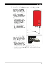
Page 11: ...ection of the protective conductor to only some parts of a machine s structure is not sufficient L brown Litz wire N blue Litz wire PE green yellow Litz wire Connect the discharging power pack 01 7926...

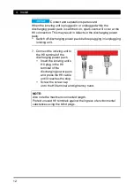
Page 12: ...power pack before plugging in unplugging ionizing unit 7 Connect the ionizing unit to the HV terminal of the discharging power pack Insert the ionizing unit s HV plug in the HV terminal of the discha...

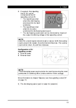
Page 13: ...e of the signalling socket NOTE Leave the unused signal socket closed or secure it with the sealing cap to prevent the ingress of environmental influences The sealing cap must be clean dry and free of...

Page 14: ...overheating thermal circuit breaker the unit must be allowed to cool down for approx 15 minutes If the defect persists refer to the following chapter Troubleshooting Refer page 18 5 1 Normal operation...

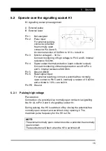
Page 15: ...o Pin 4 and 5 Internal resistance 500 Ohm Pin 5 Ground GND Pin 6 Reset signal input For external resetting connect a potential free normally open contact to Pin 5 and 6 Internally a resistor of 5 kOhm...

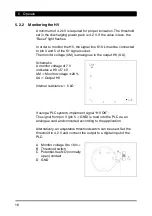
Page 16: ...to the output HV UA Schematic A monitor voltage of 7 V indicates a HV of 7 kV UM Monitor voltage 20 UA Output HV Internal resistance 5 k If using a PLC system implement signal HV OK The signal from p...

Page 17: ...ton flashes Before activating the Reset button the discharging power pack must be cooled down approx 15 minutes After the reset the HV is switched on again and the signal low level is again applied 5...

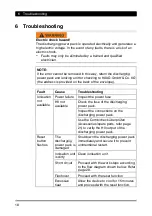
Page 18: ...ilable Power failure Inspect the power fuse HV not available Check the fuse of the discharging power pack Inspect the connections on the discharging power pack Use the Combicheck berpr fen Accessories...

Page 19: ...ever use repaired fuses Never bridge the fuse The unit type and the rated voltage are indicated on the nameplate 1 Disconnect discharging power pack from supply 2 Determine and remove the cause for th...

Page 20: ...arging power pack yes Switch off discharging power pack and connecting a ionizing unit Switch on the discharging power pack This ionizing unit has a fault Short circuit Ionizing system is ok no no no...

Page 21: ...rovided on the back of the envelope Article Illustrations Order number Circular plug K1 X 0616 Right angle plug K1 X 5718 5 m shielded signalling line K1 UL with assembled plug 06 8948 000 10 m shield...

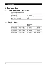
Page 22: ...igh voltage 6 7 1 kV Short circuit current Ik approx 5 mA Max pulse frequency 2 Hz 8 2 Supply voltage Unit type Nominal value Frequency range Power input 01 7924 000 230 V 10 50 60 Hz Pmax 80 VA 01 79...

Page 23: ...torage and transport 15 to 60 C Relative humidity RH Rated range of use 20 to 65 RH Limit range for storage and transport 0 to 85 RH Compressed air Rated range of use 810 hPa to 1074 hPa Vibrations Li...

Page 24: ...RNOF EI RAOF EI HRN EI HRA EI HRE EI HRAE EI PS EI PRX EI PRV EI SL EIW Type B EI VS EI VSE EI VSA EI VSAE EI VC EI VCA EI VCE EI VCAE EI VSOF EI VSAOF Ionizing bar Type A The maximum cable length KL...

Page 25: ...54 Protection type 01 7926 000 01 7927 000 IP 20 Protection class I Network supply line 01 7924 000 01 7925 000 Approx 2 6 m attached to the device Network supply line 01 7926 000 01 7927 000 Power s...

Page 26: ...ct the signalling line from the discharging power pack 5 Remove the discharging power pack from the production process 9 1 Storing Always store our products in a dry and cool place 9 2 Disposing Never...

Page 27: ......

Page 28: ...EN 9 Sine UL v01gb docx V01 28 01 2021 D 0406 GB made by...

Reviews: