background image

4    Install 


11 


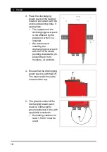
6.  Connect the discharging 

power pack to the supply 
voltage. Always connect the 
protective earth conductor 
(green-yellow) with a 
functioning protective earth 
of the mains. 
•  Connecting the PE 

conductor via parts of a 
machine body is 

insufficient. 

•  L  = brown conductor 
•  N  = blue conductor 
•  PE = green/yellow 

conductor 


Contact and separation spark-overs! 

When the ionizing unit is plugged in or unplugged while the 

discharging power pack is switched on, spark-overs will occur at the 
HV connection. This may result in defects in the discharging power 
pack. 
•  Switch off discharging power pack before plugging in/unplugging 

ionizing unit. 


7.  Connect the ionizing unit to 

the HV terminal of the 

discharging power pack. 
•  Insert the ionizing unit’s 

HV plug in the HV 
terminal of the 
discharging power pack 
and press the HV cable 
until it reaches the stop. 

•  Screw the screw cap 

onto the HV terminal and tighten by hand. 


NOTE: 

Also note the maximum connected length. 
Protect unused HV terminals against the ingress of environmental 
substances using the blind plugs. 


8.  The discharging power pack is ready for operation. 


Summary of Contents for EN 8 LC

Page 1: ...Static Line Operating instructions Discharging power pack EN 8 LC Ident number 01 7757 100 01 7756 100 Keep for future use GB...

Page 2: ......

Page 3: ...ed use 7 3 Product overview 8 4 Install 9 5 Operate 12 6 Troubleshooting 13 6 1 Replacing fuse 14 6 2 Flow chart 15 7 Accessories spare parts 16 8 Technical data 17 8 1 Characteristics and specificati...

Page 4: ...eviated HV in these operating instructions e g HV terminal The illustrations in this document are a simplified representation of the product They render only the technical facts and provide support fo...

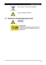
Page 5: ...ose of with household garbage Caution danger spot warning 1 2 Symbols on the discharging power pack WARNING High voltage ATTENTION Only plug in unplug the ionizing unit at the HV terminal when the dis...

Page 6: ...ack Unauthorized modifications moisture or damage to the discharging power pack may result in electric shocks or fire hazards due to sparking For reasons of safety never open or modify the discharging...

Page 7: ...tmospheres The discharging power pack is intended exclusively for the supply of alternating high voltage to HAUG ionizing units with X 2000 connector In combination with an ionizing unit electrostatic...

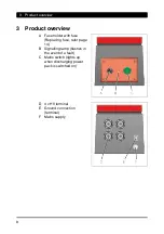
Page 8: ...iew A Fuse holder with fuse Replacing fuse refer page 14 B Signalling lamp flashes in the event of a fault C Mains switch lights up when discharging power pack is switched on D 4 x HV terminal E Groun...

Page 9: ...ontinuous overloading of the discharging power pack may result in failures Never exceed the permissible connected length Never install the discharging power pack on a surface generating or radiating h...

Page 10: ...is installed We recommend installing the discharging power pack with the HV terminals pointing downwards to protect them from moisture oil and dirt 4 Ensure that the discharging power pack is switched...

Page 11: ...spark overs will occur at the HV connection This may result in defects in the discharging power pack Switch off discharging power pack before plugging in unplugging ionizing unit 7 Connect the ionizi...

Page 12: ...wer pack using the mains switch The signalling lamp will light up briefly to confirm The mains switch will illuminate to confirm The HV is switched on 2 The discharging power pack is in operating mode...

Page 13: ...o HAUG GmbH Co KG the address is provided on the back of the envelope Fault Cause Troubleshooting Ionisation not available Mains failure Check mains fuse No HV Check fuse in discharging power pack Che...

Page 14: ...ever use repaired fuses Never bridge the fuse The unit type and the rated voltage are indicated on the nameplate 1 Disconnect discharging power pack from supply 2 Determine and remove the cause for th...

Page 15: ...s Switch off discharging power pack and connecting a ionizing unit Switch on the discharging power pack This ionizing unit has a fault Short circuit Ionizing system is ok no no no yes yes This ionizin...

Page 16: ...Accessories and spare parts can be sourced from your authorized sales partner or directly from HAUG GmbH Co KG the address is provided on the back of the envelope Article Illustrations Order number Co...

Page 17: ...specification Reference temperature 23 C HV terminals 4 High voltage 6 7 1 kV Short circuit current Ik 5 mA 8 2 Supply voltage Unit type Nominal value Frequency range Power input 01 7757 100 230 V 10...

Page 18: ...eme range for storage and transport 15 C to 60 C Humidity Rated application range 20 to 65 RF Extreme range for storage and transport 0 to 85 RF Air pressure Rated application range 800 mbar to 1060 m...

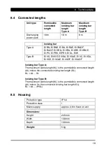
Page 19: ...B EI VS EI VSE EI VSA EI VSAE EI VC EI VCA EI VCE EI VCAE EI VSOF EI VSAOF Ionizing bar Type A The maximum cable length KL is the permissible connected length AL minus the connected ionizing bar lengt...

Page 20: ...t from the HV terminal 4 Remove the discharging power pack from the production process 9 1 Storing Always store our products in a dry and cool place 9 2 Disposing Never dispose of electrical appliance...

Page 21: ...NOTES...

Page 22: ...NOTES...

Page 23: ......

Page 24: ...EN 8 LC v02gb docx V02 22 11 2017 D 0386 GB made by...

Reviews: