background image

Page 3

For technical questions, please call 1-888-866-5797.

Item 58702 
        

Sa

FE

ty

Op

E

ra

ti

O

n

M

aint

E

nan

CE

a

SSEMBL

y

iMpOrtant SaFEty inFOrMatiOn

read all safety warnings and instructions.  

Failure to follow the warnings and instructions may result in serious injury.   

Save all warnings and instructions for future reference.

The warnings, precautions, and instructions discussed in this instruction manual cannot cover all possible 
conditions and situations that may occur.  It must be understood by the operator that common sense and 
caution are factors which cannot be built into this product, but must be supplied by the operator.

assembly Safety

1.  Keep work area clean and dry.   

Cluttered, damp, or wet work areas invite injuries.

2.  Keep children away from work area.

3.  Use eye protection.  Wear ANSI-approved safety 

impact eye goggles when assembling this Trailer.

4.  Do not modify this Trailer, and do not use this 

Trailer for a purpose for which it was not intended.

Connection Safety

1.  Dress safely while connecting/disconnecting.  

Do not wear loose clothing or jewelry, as they 
can become caught in moving parts.  Wear a 
protective hair covering to prevent long hair from 
becoming caught in moving parts.  If wearing a 
long-sleeve shirt, roll sleeves up above elbows.  
Wearing safety work shoes is recommended.

2.  Do not setup or use this Trailer if under the influence 

of alcohol or drugs.  Read warning labels on 
prescriptions to determine if your judgement or 
reflexes are impaired while taking drugs. If there 
is any doubt, do not attempt to use this Trailer.

3.  Stay alert.  Watch what you are doing at 

all times.  Use common sense.  Do not 
setup or use this Trailer when you are tired 
or distracted from the job at hand.

4.  The tail light bulbs supplied with this Trailer are for a 

12 volt DC (negative ground) electrical system only.  
Do not attempt to power the Light Bulbs with 
any other type or voltage electrical current.

5.  Make sure the Hitch Coupler (2) and the 

vehicle’s ball hitch (not included) are of equal 
mating size (2") and are rated equal to or greater 
than the weight of the Trailer and its payload.

6.  Before each use, attach the Trailer’s Safety 

Chain (1) to the towing vehicle.  Attach the Safety 
Chain to the towing vehicle’s rear bumper or 
frame with equal length on each side and chains 
crossed under the trailer tongue.  Allow just enough 
chain length for unrestricted turning.  Do not 
allow the Safety Chain to drag on the ground.

Loading Safety

1.  Do not exceed the Trailer’s maximum 

payload capacity of 1,090 lb.

2.  Properly and safely secure the payload in the Trailer.   

Load the Trailer evenly from side to side 
with 60% of the load forward of the Axle.

3.  Make sure the towing vehicle and its hitch are both 

rated to safely tow the Trailer and its payload.   
The towing capacity of the hitch is typically 
stamped on the hitch drawbar.

Summary of Contents for 58702

Page 1: ...ence 21b When unpacking make sure that the product is intact and undamaged If any parts are missing or broken please call 1 888 866 5797 as soon as possible Copyright 2021 by Harbor Freight Tools All...

Page 2: ...bol to avoid possible injury or death Indicates a hazardous situation which if not avoided will result in death or serious injury Indicates a hazardous situation which if not avoided could result in d...

Page 3: ...r use this Trailer if under the influence of alcohol or drugs Read warning labels on prescriptions to determine if your judgement or reflexes are impaired while taking drugs If there is any doubt do n...

Page 4: ...dling 1 Use the driving gear that the towing vehicle manufacturer recommends for towing 2 Drive at moderate speeds This will place less strain on your tow vehicle and trailer Trailer instability sway...

Page 5: ...s important to make sure your vehicle does not become locked in Park because of extra load on the transmission 4 Before uncoupling a trailer a Place blocks at the front and rear of the trailer tires t...

Page 6: ...ction at the beginning of this manual including all text under subheadings therein before set up or use of this trailer note For additional information regarding the parts listed in the following page...

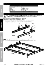
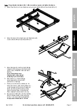
Page 7: ...g forward XVLQJ VHWV RI ROWV 0 DQG 1XWV M12 6 Leave these Bolts loose temporarily to allow proper assembly in the next steps 6 Place Axle 4 on top of Springs Align depressions on Axle with protrusions...

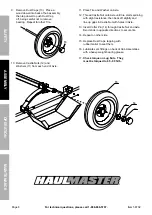
Page 8: ...1 Place Tire and Washer on Axle 12 Thread Castle Nut onto Axle until tire starts spinning with slight resistance then back off slightly and line up gaps in Castle Nut with holes in Axle 13 Insert Cott...

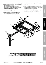
Page 9: ...ck the Coupler Trigger using its Lock Pin and R Clip 21 Attach Light Brackets 26 to Side Rails using 4 sets of Bolts M10x20 and Nuts M10 27 22 Remove nuts from back of Right Tail Light 24 Attach Right...

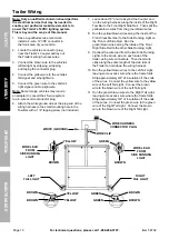
Page 10: ...Tow Bar to the Front Right Side Rail Then split the yellow brown wires from the green brown wires 8 Run the yellow brown wires along the inside of the Front Cross Member to the Side Running Light on t...

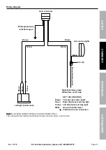
Page 11: ...clip right light Green lead Wired same as left side KEy COLOr CODES Brown tail and side marker lights Green right directional and stop light yellow Left directional and stop light White Ground to tra...

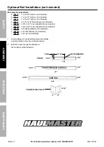
Page 12: ...not included e Qty 32 3 8 x1 3 4 Cross Head Bolt not included f Qty 32 3 8 x2 3 8 Cross Head Bolt not included g Qty 64 3 8 Spring Washer not included h Qty 64 3 8 Flat Washer not included i Qty 64 3...

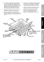
Page 13: ...End Back End Rails to the Stakes using 3 8 x2 3 8 Cross Head Bolts 3 8 Flat Washers 3 8 Spring Washers and 3 8 nuts 6 Place the Connecting Plates in position against the Side Rails and Front End Back...

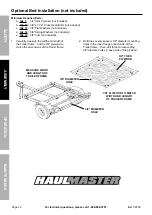
Page 14: ...Washers not included e Qty 12 3 8 nuts not included 1 Carefully measure the width and length of the Trailer frame Cut the 3 4 plywood to match the dimensions of the Trailer frame 2 Drill three evenly...

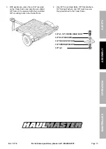
Page 15: ...wood on the Trailer frame and align the pre drilled 3 8 holes in the plywood with the pre drilled 3 8 mounting holes in the Trailer frame 4 Use 3 8 Cross Head Bolts 3 8 Flat Washers 3 8 Spring Washers...

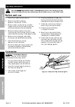
Page 16: ...r jack tongue support and any attached stabilizers sold separately are raised and locked in place 8 Check load distribution to make sure the tow vehicle and Trailer are properly balanced front to back...

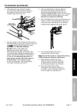
Page 17: ...oving This adjustment should be done by two people If the Adjusting Nut is too tight the Handle will not lock 6 After the Adjusting Nut is properly adjusted pull back on the Trigger and push down on t...

Page 18: ...is rated to carry Maximum loaded vehicle weight means the sum of a Curb weight b Accessory weight c Vehicle capacity weight and d Production options weight Maximum tire width means the greater of eith...

Page 19: ...s are the plant code where it was manufactured and the last four numbers represent the week and year that the tire was built For example the numbers 2107 mean the 21st week of 2007 Any other numbers u...

Page 20: ...re In general the greater the number of plies the more weight a tire can support Tire manufacturers also must indicate the materials in the tire which include steel nylon polyester and others Maximum...

Page 21: ...placard certification label or in the owner s manual This Trailer has 80 PSI recommended cold tire inflation pressure 2 Measure and record the tire pressure of all tires 3 If the tire pressure is too...

Page 22: ...le to maintain traction properly and stopping distance will be increased significantly Operation Safety note Selected recommendations in this section are adapted from TOWING A TRAILER Being Equipped f...

Page 23: ...bility you may need when backing up have someone outside at the rear of the trailer to guide you whenever possible 4 Use slight movements of the steering wheel to adjust direction Exaggerated movement...

Page 24: ...cle or trailer Lubricate Wheel Bearings 1 EVEry 2 000 tO 3 000 MiLES OF USE lubricate zerk fittings on back of Hub Assemblies with a heavy weight bearing grease WarninG Whenever a hub is disassembled...

Page 25: ...lights off then clean surface deposits in connector holes Lubricate lightly with dielectric light waterproof grease pLEaSE rEaD tHE FOLLOWinG CarEFULLy THE MANUFACTURER AND OR DISTRIBUTOR HAS PROVIDED...

Page 26: ...Description Qty 1 7 32 Safety Chain 1 2 1 7 8 Coupler 1 3 Tow Bar 1 4 Axle 1 5 Leaf Spring 2 6 Hex Bolt M12x80 and Nut M12 4 7 Spring Plate 2 8 Axle U Bolt M10x90 and Nut M10 4 9 Hub Assembly 2 10 Be...

Page 27: ...e 27 For technical questions please call 1 888 866 5797 Item 58702 SaFEty OpEratiOn MaintEnanCE aSSEMBLy assembly Diagram 30 29 1 2 3 4 5 6 7 8 9 10 11 12 13 14 15 16 17 18 25 19 20 21 22 23 24 26 27...

Page 28: ...p for the period of 90 days from the date of purchase This warranty does not apply to damage due directly or indirectly to misuse abuse negligence or accidents repairs or alterations outside our facil...

Reviews: