HAULOTTE GROUP
9 AXLE AND RELATED COMPONENTS
129
MAINTENANCE (CONTINUED)
TABLE 9-6. MAGNET AMPERES CHART
Brake Size
Amps / Magnet
Two Brakes
Four Brakes
Six Brakes
Magnet / Ohms
7” x 1 1/4”
2.5
5.0
10.0
15.0
3.9
10” x 1 1/2”
3.0 6.0
12.0
18.0
3.2
10” x 2 1/4”
3.0
6.0
12.0
18.0
3.2
12” x 2”
3.0
6.0
12.0
18.0
3.2
12” x 2 1/2”
3.0
6.0
12.0
18.0
3.2
12” x 3 3/8”
3.0
6.0
12.0
18.0
3.2
If a resistor is used in the brake system, it must be set at zero or
bypassed completely to obtain the maximum amperage reading.
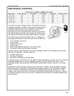
Individual amperage draw can be measured by inserting the
ammeter in the line at the magnet you want to check.
Disconnect one of the magnet lead wire connectors and attach
the ammeter between the two wires. Make sure that the wires
are properly reconnected and sealed after testing is competed.
The most common electrical problem is low or no voltage and
amperage at the brakes. Common causes of this condition are:
1. Poor electrical connections
2. Open circuits
3. Insufficient wire size
4. Broken wires
5. Blown fused (fusing of brakes is not recommended)
6. Improperly functioning controllers or resistors
Another common electrical problem is shorted or partially shorted circuits (indicated by abnormally
high system amperage). Possible causes are:
1. Shorted magnet coils
2. Defective controllers
3. Bare wires contacting a grounded object
Finding the cause of a short circuit in the system is done by isolating one section at a time. If the high
amperage reading drops to zero by unplugging the trailer, then the short is in the trailer. If the
amperage reading remains high with all the brake magnets disconnected, the short is in the trailer
wiring.
All electrical trouble shooting procedures should start at the controller. Most complaints regarding
brake harshness or malfunction are traceable to improperly adjusted or non-functioning controllers.
See your controller manufacturer’s data for proper adjustment and testing procedures. For best
results, all the connection points in the brake wiring should be sealed to prevent corrosion. Loose or
corroded connectors will cause an increase in resistance which reduces the voltage available for the
brake magnets.
Summary of Contents for 3522A
Page 1: ...OPERATOR S MAINTENANCE MANUAL B33 01 0093 Rev 4 May 2013...
Page 76: ...HAULOTTE GROUP 6 DECAL REPLACEMENT 76 DECAL KIT ANSI...
Page 78: ...HAULOTTE GROUP 6 DECAL REPLACEMENT 78 IDENTIFICATION PLATES OPTIONAL EQUIPMENT ANSI...
Page 84: ...HAULOTTE GROUP 6 DECAL REPLACEMENT 84 DECAL KIT CE...
Page 86: ...HAULOTTE GROUP 6 DECAL REPLACEMENT 86 IDENTIFICATION PLATES OPTIONAL EQUIPMENT CE...
Page 88: ...HAULOTTE GROUP 6 DECAL REPLACEMENT 88 DECAL KIT AU...
Page 90: ...HAULOTTE GROUP 6 DECAL REPLACEMENT 90 IDENTIFICATION PLATES OPTIONAL EQUIPMENT AU...
Page 92: ...HAULOTTE GROUP 6 DECAL REPLACEMENT 92...
Page 106: ...HAULOTTE GROUP 8 MATERIAL SAFETY 106 MATERIAL SAFETY DATA SHEET POWERFLOW AW HVI HYDRAULIC OIL...


