HAULOTTE GROUP
5
LIST OF ILLUSTRATIONS
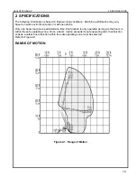
Figure 2-1. Range of Motion............................................................................................................... 15
Figure 3-1. Ground (Lower) Control Panel ......................................................................................... 22
Figure 3-2. Platform (Upper) Control Panel........................................................................................ 25
Figure 3-3. Boom Travel Latches ....................................................................................................... 28
Figure 3-4. Outrigger Control Panel ................................................................................................... 29
Figure 3-5. Hand Pump Controls for Manual Operation..................................................................... 31
Figure 3-6. Location of Lift Cylinders for Manual Boom Lowering...................................................... 32
Figure 3-7. Location of Manual Lowering Valves. .............................................................................. 32
Figure 3-8. Trailer Hitching................................................................................................................. 34
Figure 3-9. Lifting the Aerial Work Platform ....................................................................................... 35
Figure 3-10. Transport the Aerial Work Platform................................................................................. 36
Figure 4-1. Battery Charger Faceplate............................................................................................... 38
Figure 4-2. Outrigger Position Switch................................................................................................. 41
Figure 4-3. Hydraulic Reservoir.......................................................................................................... 42
Figure 4-4. Wheel Nut Tightening Sequence ..................................................................................... 44
Figure 4-5. Display Run Time Hours ................................................................................................. 45
Figure 4-6. Machine Position for Slew Ring Measurement ............................................................... 46
Figure 4-7. Slew Ring Position Measurement ................................................................................... 46
Figure 4-8. Platform Position After Rotation...................................................................................... 46
Figure 4-9. Position Machine for Leveling .......................................................................................... 48
Figure 4-10. Level Sensor Digitally Based .......................................................................................... 48
Figure 4-11. Level Sensor Pendulum Based....................................................................................... 48
Figure 4-12. Ground (Lower) Control Panel for Leveling System....................................................... 49
Figure 4-13. Platform Position............................................................................................................ 50
Figure 4-14. Ground (Lower) Control Panel for Overload Protection ................................................. 50
Figure 4-16. Manual Outrigger Control Wire Harness........................................................................ 53
Figure 4-17. Bottom Side of the Ground (lower) Control Box.............................................................. 53
Figure 4-18. Hydraulic Power Unit ..................................................................................................... 53
Figure 4-19. Attaching the Pressure Gauge to the Hydraulic Power Unit. ......................................... 54
Figure 4-15. Motor Controller ............................................................................................................. 67
Figure 5-1. Location of Master Cylinder ............................................................................................. 69
Figure 5-2. Location of Slave Cylinder ............................................................................................... 70
Figure 5-3. Location of Manual Lowering Valves ............................................................................... 71
Figure 5-4. Push “Button” Lowering Valve ......................................................................................... 71
Figure 5-5. Lift Cylinder Replacement................................................................................................ 71
Figure 5-6. Outrigger Cylinder Replacement...................................................................................... 73
Figure 5-7. Cylinder Valve Removal................................................................................................... 73
Figure 7-1. Drive and Set Controls..................................................................................................... 94
Figure 7-2. Disconnect Plug from Load Sense Module...................................................................... 97
Figure 7-3. Remove Platform (Upper) Control Box. ........................................................................... 97
Figure 7-4. Loopback plug.................................................................................................................. 97
Figure 7-5. Platform Removal ............................................................................................................ 98
Figure 7-6. Material Lifting Hook Installation ...................................................................................... 98
Figure 7-7. Material Lift “Stowed” Position ......................................................................................... 99
Figure 7-8. Material Lift “In Use” Position........................................................................................... 99
Figure 7-9. Manual Platform Rotator ................................................................................................ 100
Figure 9-1. Standard Brake Adjustment Procedure ......................................................................... 137
Figure 9-2. Drive & Set Brake Adjustment Procedure...................................................................... 139
Summary of Contents for 3522A
Page 1: ...OPERATOR S MAINTENANCE MANUAL B33 01 0093 Rev 4 May 2013...
Page 76: ...HAULOTTE GROUP 6 DECAL REPLACEMENT 76 DECAL KIT ANSI...
Page 78: ...HAULOTTE GROUP 6 DECAL REPLACEMENT 78 IDENTIFICATION PLATES OPTIONAL EQUIPMENT ANSI...
Page 84: ...HAULOTTE GROUP 6 DECAL REPLACEMENT 84 DECAL KIT CE...
Page 86: ...HAULOTTE GROUP 6 DECAL REPLACEMENT 86 IDENTIFICATION PLATES OPTIONAL EQUIPMENT CE...
Page 88: ...HAULOTTE GROUP 6 DECAL REPLACEMENT 88 DECAL KIT AU...
Page 90: ...HAULOTTE GROUP 6 DECAL REPLACEMENT 90 IDENTIFICATION PLATES OPTIONAL EQUIPMENT AU...
Page 92: ...HAULOTTE GROUP 6 DECAL REPLACEMENT 92...
Page 106: ...HAULOTTE GROUP 8 MATERIAL SAFETY 106 MATERIAL SAFETY DATA SHEET POWERFLOW AW HVI HYDRAULIC OIL...


