121
4000429690
E 11.15
US / GB
OPTIMUM 8 - OPTIMUM 1931 E
E
- Trouble shooting and diagram
Failure
Code
C
Description
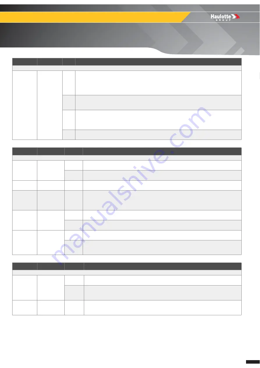
F02 : Contactor
Power
contactor
SB801
F02.04 (D)
1
The driver of main contactor drive coil is shorted, or its coil is disconnected.
Ensure there is no short or low-impedance pull-down between MC and -Vbatt.
Check connections and wiring for interruptions of MC DRIVE coil.
If wiring and connection are correct, the problem is in the controller : Replace it.
2
The main contactor coil has been driven by the controller, but the contactor does not close.
Check the contact in the main contactor drive contactor and if it is not working, replace the
main contactor drive.
4
Before driving the LC coil, the controller checks if the contactor is stuck. The controller drives
the bridge for some tens milliseconds, trying to discharge the capacitors bank. If they don't
discharge the fault condition is entered.
Check the power contact of the main contactor drive and replace it if necessary.
8
Supervisor status is ALARM or WAIT RESET and main contactor is not forced open.
Key OFF / ON.
Failure
Code
C
Description
F04 : Electrovalves
Steering
YV121 /
YV122
F04.01 (D)
1
Short circuit detected on steering front left electro valve :
--> YV121 = FAIL
2
Short circuit detected on steering front right electro valve :
--> YV122 = FAIL
Arm
YV420
F04.04 (D)
1
Short circuit detected on arm descent electro valve :
--> YV420 = FAIL
Principal
movement
s
YV903
F04.11 (D)
1
Short circuit detected on pothole extend electro valve :
--> YV903 = FAIL
Potholes
YV121 /
YV122
F04.40 (D)
1
Short circuit detected on arm descent electro valve :
--> YV122 = FAIL
2
Short circuit detected on pothole retract electro valve :
--> YV121 = FAIL
Movement
Selection
Valve
YV121 /
YV122
F04.41 (D)
1
Short circuit detected on steering / potholes selection electro valve :
--> YV120 = SHORT CIRCUIT FAILURE
2
Open circuit detected on steering / potholes selection electro valve :
--> YV120 = OPEN CIRCUIT FAILURE
Failure
Code
C
Description
F05 : Joystick
Arm /
Drive
Joystick
SM901
F05.01 (D)
1
Analog signal SM901 is out of allowed range :
--> SM901 < 0.2 V | SM901 > 4.8 V
2
Incoherence between analogue signal and out of neutral signals for SM901 joystick :
--> SM901N = 1 & (2,45V < SM901Y < 2,55V)
or--> SM901N =0 & (SM901Y < 2.0V | SM901Y > 3.0V)
Joystick
Neutral
SM901
F05.11 (D)
1
Neutral position of arm and drive joystick SM901 not detected after upper control box
selection :
--> SM901 < 2.35V | SM901 > 2.65V
Summary of Contents for OPTIMUM 1931 E
Page 2: ...2 4000429690 E 11 15 US GB OPTIMUM 8 OPTIMUM 1931 E...
Page 10: ...10 4000429690 E 11 15 US GB OPTIMUM 8 OPTIMUM 1931 E A Preface Foreword Notes...
Page 19: ...19 4000429690 E 11 15 US GB OPTIMUM 8 OPTIMUM 1931 E C Familiarization Familiarization Notes...
Page 54: ...54 4000429690 E 11 15 US GB General data Structural part inspection MS0001 Notes...
Page 64: ...64 4000429690 E 11 15 US GB General data Breaking test procedure MS0004 Notes...
Page 72: ...72 4000429690 E 11 15 US GB Electric Electrical wiring MS0025 Notes...
Page 76: ...76 4000429690 E 11 15 US GB Scissor arm Scissor arms screw Periodical checks MS0073 Notes...
Page 88: ...88 4000429690 E 11 15 US GB Platform Removal replacement of platform assembly MS0095 Notes...
Page 98: ...98 4000429690 E 11 15 US GB Scissors Removal replacement of Scissor pack MS0096 Notes...
Page 102: ...102 4000429690 E 11 15 US GB Chassis Calibration steering MS0097 Notes...
Page 116: ...116 4000429690 E 11 15 US GB Ground control box HAULOTTE Activ Screen MS0106 Notes...
Page 135: ...135 4000429690 E 11 15 US GB OPTIMUM 8 OPTIMUM 1931 E E Trouble shooting and diagram...
Page 136: ...136 4000429690 E 11 15 US GB OPTIMUM 8 OPTIMUM 1931 E E Trouble shooting and diagram...
Page 138: ...138 4000429690 E 11 15 US GB OPTIMUM 8 OPTIMUM 1931 E E Trouble shooting and diagram Notes...
Page 148: ...148 4000429690 E 11 15 US GB OPTIMUM 8 OPTIMUM 1931 E F Records...


