80
4000429690
E 11.15
US / GB
Chassis
Removal / replacement of steering pivot assembly
MS0090
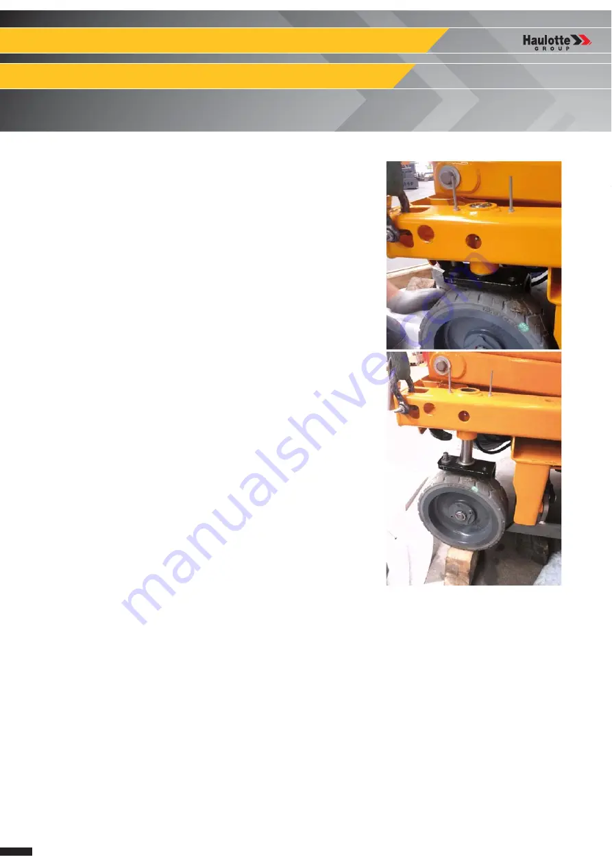
Removing the steering pivot :
• Place a block under the pivot (or wheel) so the assembly does not fall
out on the ground when the upper plate is unscrewed.
• Unscrew the 2 cap head bolts on the top of the pivot. Attention, the
pivot is no longer fixed in the chassis.
• Slide the assembly down and out of the chassis.
• Remove the thrust washer from the top of the pivot.
• Unscrew the axle nut and remove the wheel (if wheel is to be
removed).
Summary of Contents for OPTIMUM 1931 E
Page 2: ...2 4000429690 E 11 15 US GB OPTIMUM 8 OPTIMUM 1931 E...
Page 10: ...10 4000429690 E 11 15 US GB OPTIMUM 8 OPTIMUM 1931 E A Preface Foreword Notes...
Page 19: ...19 4000429690 E 11 15 US GB OPTIMUM 8 OPTIMUM 1931 E C Familiarization Familiarization Notes...
Page 54: ...54 4000429690 E 11 15 US GB General data Structural part inspection MS0001 Notes...
Page 64: ...64 4000429690 E 11 15 US GB General data Breaking test procedure MS0004 Notes...
Page 72: ...72 4000429690 E 11 15 US GB Electric Electrical wiring MS0025 Notes...
Page 76: ...76 4000429690 E 11 15 US GB Scissor arm Scissor arms screw Periodical checks MS0073 Notes...
Page 88: ...88 4000429690 E 11 15 US GB Platform Removal replacement of platform assembly MS0095 Notes...
Page 98: ...98 4000429690 E 11 15 US GB Scissors Removal replacement of Scissor pack MS0096 Notes...
Page 102: ...102 4000429690 E 11 15 US GB Chassis Calibration steering MS0097 Notes...
Page 116: ...116 4000429690 E 11 15 US GB Ground control box HAULOTTE Activ Screen MS0106 Notes...
Page 135: ...135 4000429690 E 11 15 US GB OPTIMUM 8 OPTIMUM 1931 E E Trouble shooting and diagram...
Page 136: ...136 4000429690 E 11 15 US GB OPTIMUM 8 OPTIMUM 1931 E E Trouble shooting and diagram...
Page 138: ...138 4000429690 E 11 15 US GB OPTIMUM 8 OPTIMUM 1931 E E Trouble shooting and diagram Notes...
Page 148: ...148 4000429690 E 11 15 US GB OPTIMUM 8 OPTIMUM 1931 E F Records...


