background image

38

 4000429690 

E 11.15  

US / GB

OPTIMUM 8 - OPTIMUM 1931 E

D

- Inspection and maintenance schedule

3 -  Daily inspection

The content and method of inspection must be conducted by operators before using the machine, it includes a
visual inspection and functional and security systems testing of the machine. 

This inspection is the responsibility of the user. 

Each day and before the beginning of a new work period and with each change of operator, the machine must
be subjected to a visual inspection and a complete functional test.  This inspection is called Daily Inspection. 

Any repairs required must be performed before the machine is used, its correct operation depends on it. 

To tighten loosened hardware, refer to recommended torque value table in maintenance book. 

In case of leaks, tighten or replace the damaged part before placing the machine in service. 

In case of structural part deformation, cracks, broken weld, paint chipped, replace the part before placing the
machine in service. 

S a m p l e   o f   b r o k e n   w e l d s

Inspection Forms are provided to assist your inspection process. 

We recommend these forms to be completed daily and stored to assist with your maintenance schedule. 

Each action is depicted in the daily inspection sheet using the following symbols. 

Visual inspection without 
disassembly

Lubrication-Greasing

Functional adjustments

To drain off

To check by test

Tightening

Levelling

Systematic replacement

Visual inspection with small 
disassembly or movement 
needed to reach the part.  
Replacement is necessary. 

Proof tests.  Need HAULOTTE Services® authorization.  For countries 
where machines are not subject to controlled periodic maintenance. 

Summary of Contents for OPTIMUM 1931 E

Page 1: ...Maintenance Book OPTIMUM 8 OPTIMUM 1931 E 4000429690 E 11 15 US GB Maintenance Book OPTIMUM 8 OPTIMUM 1931 E USA...

Page 2: ...2 4000429690 E 11 15 US GB OPTIMUM 8 OPTIMUM 1931 E...

Page 3: ...utionHazards 13 1 4 Explosion FireHazards 14 2 Maintenance and repair training 15 2 1 Owner sresponsability 15 2 2 Technician sresponsability 15 2 3 HAULOTTEServices 15 2 4 Training 15 2 5 Productmodi...

Page 4: ...3 2 1 LCD screen 24 1 4 Platformcontrolbox 28 1 4 1 Layout 28 2 Device layout 30 2 1 Sensorsandactuators 30 3 Power source Engine specifications 96 4 Consumables 31 5 Ingredient 32 5 1 Hydraulicoil 3...

Page 5: ...n 55 MS0003 Cylinder inspection 59 MS0004 Breaking test procedure 63 MS0005 Torque Values 65 MS0020 Hoses inspection Replacement 69 MS0025 Electrical wiring 71 MS0072 Pressure adjustment 73 MS0073 Sci...

Page 6: ...17 1 1 Recommendations 117 1 2 Description 117 1 3 Requirements 117 2 Legend 130 2 1 Platformcontrolbox 130 2 2 Systemarchitecture 131 2 2 1 Power circuit 132 2 2 2 Control circuit 133 3 Electric diag...

Page 7: ...he equipment within the performance limits With regard to the designation of our equipment we stress that this is purely for commercial purposes and not to be con fused with the technical specificatio...

Page 8: ...y level when operating or maintaining the Aerial Work Platform S y m b o l Symbol Description Danger Risk of injury or death Caution Risk of material damage Prohibition relating to work safety and qua...

Page 9: ...NG THE MACHINE Color Title Description Danger Indicates a hazardous situation which if not avoided WILL result in death or serious injury Warning Indicates a hazardous situation which if not avoided C...

Page 10: ...10 4000429690 E 11 15 US GB OPTIMUM 8 OPTIMUM 1931 E A Preface Foreword Notes...

Page 11: ...e machine during maintenance is strictly forbidden Do not climb onto the covers The handling of parts must be carried out using appropriate equipment Chains Lifting slings Lifting anchors Plug the end...

Page 12: ...intain clearance from high voltage lines Maintain clearance from generators radar electromagnetic fields Never expose the batteries or electrical components to water high pressure washer rain Never to...

Page 13: ...e machine when close to live power lines consider the movement of the machine and the sway of the electric power lines particularly in windy conditions Do not operate the machine during lightning thun...

Page 14: ...IS NEUTRALIZED WITH SODIUM BICARBONATE AND WATER Do not start the engine if you smell or detect liquid propane gas LPG gasoline diesel fuel or other explosive substances Do not work in an explosive o...

Page 15: ...nd the decals affixed on the machine The technician must inform the owner or hirer if the manual or any decals are missing or in poor condition and of any malfunction of the machine 2 3 HAULOTTE SERVI...

Page 16: ...he machine model and serial number When ordering any consumables or spare parts please use this manual and the HAULOTTE Essential catalogue to receive your genuine HAULOTTE spare parts your only guara...

Page 17: ...e hour meter whenever an intervention is made The engine hour meter must be maintained in good working order to guarantee maximum working life and to justify maintenance at the recommended time Warran...

Page 18: ...herefore not be covered by the warranty agreement 3 4 WARRANTY CONDITIONS To benefit from the warranty the owner or rental company must inform the nearest HAULOTTE subsidiary or the subsidiary that de...

Page 19: ...19 4000429690 E 11 15 US GB OPTIMUM 8 OPTIMUM 1931 E C Familiarization Familiarization Notes...

Page 20: ...TIMUM 8 OPTIMUM 1931 E C Familiarization 1 Primary machine components 1 1 LAYOUT O P T I M U M 8 O P T I M U M 1 9 3 1 E C35 C171 C77 C168 C141 C7 C75 C78 C20 C2 C78 C58 C30 C42 C76 C81 C82 C6 C85 C1...

Page 21: ...yard attachment points C58 Pothole protection C168 Maintenance support C64 Tilt sensor C169 Folding guardrails Optional Not shown C75 Extension desk C171 Scissors lifting cylinder C76 Guardrail The ma...

Page 22: ...d in De energizes control system 43 Horn button Not used 92 Control box activation key selector Right Ground control box energized Center De energizes control system Left Platform control box energize...

Page 23: ...scription Function 1 Platform raising control Platform raises 2 LCD screen Display status of operation of the machine 3 Navigation button Navigation in the menus Scroll up 4 Confirmation button Valida...

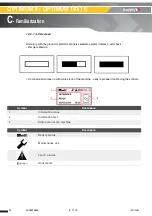
Page 24: ...orm controls selected system initiates a self check Bar gets filled up Home screen comes on with status icon of the machine okay to proceed functioning the controls Symbol Description 1 Information ic...

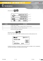
Page 25: ...for entering the access code Validation by pressing on is active only if access code is known and entered refer to maintenance manual for the procedure for the different level code useage Symbol Descr...

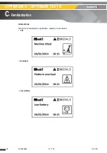
Page 26: ...26 4000429690 E 11 15 US GB OPTIMUM 8 OPTIMUM 1931 E C Familiarization Alarm status Alarm status displayed as applicable samples shown below Tilt Overload Low battery...

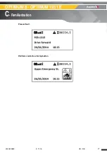
Page 27: ...27 4000429690 E 11 15 US GB OPTIMUM 8 OPTIMUM 1931 E C Familiarization Present fault Platform control box E stop button...

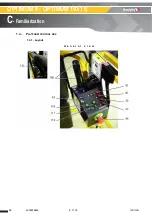
Page 28: ...28 4000429690 E 11 15 US GB OPTIMUM 8 OPTIMUM 1931 E C Familiarization 1 4 PLATFORM CONTROL BOX 1 4 1 Layout G e n e r a l v i e w...

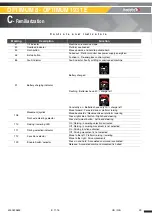
Page 29: ...arge left Constantly on Batteries have only 20 charge left 108 Movement joystick Move forward Forward drive or platform raising Move backwards Reverse drive or platform lowering Front axle steering se...

Page 30: ...30 4000429690 E 11 15 US GB OPTIMUM 8 OPTIMUM 1931 E C Familiarization 2 Device layout 2 1 SENSORS AND ACTUATORS S e n s o r s a n d a c t u a t o r s...

Page 31: ...potentiometer SR150 Tilt sensor low position SR420 Pothole limit sensor SR722 6 tracks 23 position for potholes or steering switch priority for potholes YV120 Right steering or pothole entry valve YV...

Page 32: ...g requirements Ambient operating temperature between 15 C 9 F and 40 C 104 F HEES type biodegradable oil only according to standards ISO 15380 and VDMA 24568 Necessary characteristics Ingredient HAULO...

Page 33: ...E C Familiarization 5 Lubrication diagram L i s t o f i n g r e d i e n t s 5 1 GREASING POINTS LOCALIZATION Ingredient Symbol HAULOTTE code Extreme pressure lithium grease 2820304320 Front right whe...

Page 34: ...are not equal to the following Do not use the machine Setting updating is needed Always check speed movement from the ground control box OPTIMUM 8 OPTIMUM 1930 E Folded machine maximum speed 4 5 km h...

Page 35: ...must be carried out by a competent technician whose selection is under the responsibility of the manager Company employee or other Maintenance operations performed must be recorded in a register log...

Page 36: ...36 4000429690 E 11 15 US GB OPTIMUM 8 OPTIMUM 1931 E D Inspection and maintenance schedule Hydraulic oil Hydraulic oil filter Adjusting the hydraulic pressure Scissors Screw ring...

Page 37: ...rseen by the company manager This register or machine log book and the list of competent repair persons must be made available to the Government Work Inspector and company safety committee at any time...

Page 38: ...alue table in maintenance book In case of leaks tighten or replace the damaged part before placing the machine in service In case of structural part deformation cracks broken weld paint chipped replac...

Page 39: ...rol boxes are clean and legible Operation of start stop device Operation of E stop button device Operation of enable switch Operation of horn from platform control box Operation of movement from platf...

Page 40: ...All compartments covers open and lock properly Pin pin stop bearing No bent cracked or broken pins pin stops bushes or bearings Cylinder and hydraulic component pumps filters manifold No leaks on the...

Page 41: ...operly Pothole safety device operate properly if equipped Test of load sensing system visual warning at control box Check that the safety devices operates correctly Emergency stop Enable switch Fault...

Page 42: ...n every 125 hours This inspection should include the daily inspection Intervention to be made after Extensive dismantling and reassembly Repairs involving the machine s essential components Any accide...

Page 43: ...ox Operation of emergency lowering device Work Platform Floor guardrails access and extensions No cracks broken weld paint chipped No deterioration and visible damage Harness anchor points are not cra...

Page 44: ...earing No abrasion damage or oxidation of pin pin stop bushes and bearing No radial gap 0 5mm on the pin No bent cracked or broken pins pin stops bushes or bearings Position and state of bushes and be...

Page 45: ...speed limiting device operate properly Pothole safety device operate properly if equipped Test and if needed adjustment of load sensing system Presence and good operation of sensors Sensors and safety...

Page 46: ...ons For details refer to daily and periodic inspections listed earlier 1 Increase in periodic inspections 2 For countries where machines are not subject to controlled periodic maintenance Symbo l Desc...

Page 47: ...erioration and visible damage No abnormal gap in joints and slides No screws missing loose parts Frame axle steering system stabilizers arms No deterioration and visible damage No foreign body in join...

Page 48: ...1 Increase in periodic inspections 2 For countries where machines are not subject to controlled periodic maintenance Symb ol Description Symb ol Description Visual inspections Systematic replacement...

Page 49: ...s authorization For countries where machines are not subject to controlled periodic maintenance Yes No Corrected Not applicable Frame axle steering system stabilizers arms No deterioration and visible...

Page 50: ...50 4000429690 E 11 15 US GB OPTIMUM 8 OPTIMUM 1931 E D Inspection and maintenance schedule Notes...

Page 51: ...INSPECTION Standard tool kit Protective goggles Gloves Place barriers around the perimeter of the work area Exclusively use tools and auxiliary average adapted Always wear necessary safety clothing Fo...

Page 52: ...tive checks The criteria quoted above are applicable The main items to be inspected are Boss welds on chassis turret arms booms and jib Booms and arms welds E x a m p l e In the event of suspicion of...

Page 53: ...ts without jolts while supporting the load All the security device function correctly Authorized maximum speeds of operation are not exceeded Refer to the user manual for the description of the safety...

Page 54: ...54 4000429690 E 11 15 US GB General data Structural part inspection MS0001 Notes...

Page 55: ...Check absence of heavy abrasion wear or oxidation of the pins stops pins All 250 h or 6 months Reinforced visual inspection with disassembling of certain elements to reach the bushes or bearing In ad...

Page 56: ...ovements of the structure Prolonged storage of the machine 6 months Specific storage and use Environment strong moisture and salinity of the air 4 Criteria of replacement The pins stop pins bushes and...

Page 57: ...ousing must be correctly aligned during the assembly process The recommended values for the bearing drift are given on the diagram below R e c o m m e n d e d V a l u e s After inserting the bearing l...

Page 58: ...espect the following stages Clean boring and or the pins to remove all the foreign bodies Slightly lubricate boring and or pins Lubricate the ring of the bearing slightly To fit bearing in a boring ta...

Page 59: ...ed back completely and operational 3 Control and maintenance 3 1 VISUAL INSPECTIONS The hydraulic actuating cylinders must be subjected to visual inspections periodic all the 250 hours or 6 months suc...

Page 60: ...linder Lift the concerned equipment boom or jib of approximately half way Extend the telescope to its maximum Telescoping cylinder Lift the boom to its maximum angle and telescope approximately 50 cm...

Page 61: ...m 85 ft4 in After 10 mn creep 0 2 mm 7874 in After 60 mn creep 1 mm 0 039 in Outriggers cylinder Oscillating axle locking Lift cylinder arm or boom Machine with range limiting system After 10 mn creep...

Page 62: ...sassembling of the element to check the entirety of the welding Each Cylinder must be disassembled and must be review using non destructive checks The criteria quoted above are applicable Absence of d...

Page 63: ...rs or every 6 months High speed On a flat ground or slightly inclined always lower than the authorized slope see plate manufacturer Trace on the ground a line being used as reference mark of stop Roll...

Page 64: ...64 4000429690 E 11 15 US GB General data Breaking test procedure MS0004 Notes...

Page 65: ...1 Metric torque chart For screws HAULOTTE use columns A B and C Screw 1 grey dull dry use colums A Screw 1 grey dull greasy use column B Screw 2 yellow dry use column C Screw 2 yellow greasy use colu...

Page 66: ...Nm ft lbs Nm ft lbs Nm ft lbs Nm 8 5 9 8 5 4 7 41 7 2 9 88 16 2 22 14 19 1 18 8 25 5 23 6 32 20 1 27 3 26 9 36 5 28 38 23 6 32 31 4 42 6 10 12 1 7 16 5 10 8 14 7 14 4 19 6 32 4 5 44 27 9 37 8 37 2 50...

Page 67: ...42 33 44 7 44 59 6 38 51 5 24 26 35 2 35 47 4 37 50 1 49 66 4 43 58 3 7 16 14 37 50 1 49 66 4 50 67 8 70 94 7 61 62 7 20 41 55 5 55 74 5 60 81 3 80 108 4 68 92 1 1 2 13 57 77 3 75 101 6 80 108 4 110...

Page 68: ...1640 2223 2190 2969 2670 3620 3560 4826 3000 4067 Sub assemblies Concerned elements Torque Axles Wheels 320 Nm Wheel studs Driving reducer Loctite 243 Normal threadlocker Hydraulic motor Driving reduc...

Page 69: ...to replace the elements by respecting the following recommendations 3 Hoses Disassembling For safety reasons respect imperatively the following conditions of disassembling Fold the machine on a flat...

Page 70: ...e fixing of the hoses respect the tightening torques below T i g h t e n i n g t o r q u e t a b l e Once all the hoses are correctly tight Put the machine in operational configuration Carry out some...

Page 71: ...ydraulic manifold wiring Hydraulic manifold wiringInspect for a liberal coating of dielectric grease at the following location All wire harnesses connectors to the ground control box Start the engine...

Page 72: ...72 4000429690 E 11 15 US GB Electric Electrical wiring MS0025 Notes...

Page 73: ...be done in work before intervening on and near the machine After completion of work all the covers and safety devices must be positioned back completely and operational 3 Pressure adjustment To allow...

Page 74: ...74 4000429690 E 11 15 US GB Hydraulics Pressure adjustment MS0072 4 Pressure plug location G e n e r a l p r e s s u r e i n t a k e Marking Description 1 Pressure reading 2 Pressure relief valve...

Page 75: ...t unscrewing perform tightening with a torque wrench torque de 22 N m Standard tool kit Protective goggles Gloves Torque spanner Tightening torques 22 N m Place barriers around the perimeter of the wo...

Page 76: ...76 4000429690 E 11 15 US GB Scissor arm Scissor arms screw Periodical checks MS0073 Notes...

Page 77: ...2 Plan of the assembly P l a n o f t h e a s s e m b l y Standard tool kit Protective goggles Gloves Overhead crane or equivalent 1 T 1 205 lb capacity minimum Torque wrench for 10 Nm 80 Nm and 250 Nm...

Page 78: ...IFFICULT TO HOLD THE WHEEL Isolate the main power by activating the battery isolation switch and disconnect any other sources of electrical energy battery charger for example Lift the machine approx 2...

Page 79: ...79 4000429690 E 11 15 US GB Chassis Removal replacement of steering pivot assembly MS0090 Removing the steering bar from the pivot Remove the circlip and washer Slide the bar up off the pin...

Page 80: ...so the assembly does not fall out on the ground when the upper plate is unscrewed Unscrew the 2 cap head bolts on the top of the pivot Attention the pivot is no longer fixed in the chassis Slide the...

Page 81: ...NLY POSSIBLE IF THE WHEEL IS ALREADY REMOVED Removing the axle from the pivot Place the assembly face down on a flat surface Using a screwdriver and soft hammer remove the dust cover Remove the circli...

Page 82: ...ng nut tensions Nut on the inner axle 250 Nm 6 cap head screws on the top of the wheel pivot 10 Nm Wheel nut 80 Nm then continue tightening to the next tab on the lock washer 5 Complementary operation...

Page 83: ...E decal near the start stop button to inform personnel that work is currently in progress on the equipment Beware of the risk of burns the hydraulic system operates at high temperatures The pressure i...

Page 84: ...pper control box 1 near plug and 2 on the vertical part towards the upper control box Remove the upper control box With the extension deck fully retracted unscrew the 4 cap head screws that hold the m...

Page 85: ...NTACT THE TOP OF THE REAR SCISSOR ARMS WHEN BEING REMOVED Attach the slings to the mid rail of the platform front and rear like shown on the following foto 1 1 x sling 2 m 6 ft 7 in 500 kg 1 103 lb mi...

Page 86: ...SLIGHTLY SHORTER IN LENGTH Using the overhead crane slide the platform towards the rear N B AFTER THE PLATFORM IS MORE THAN 1 2 WAY LOWER THE CRANE GENTLY TO RAISE THE FRONT OF THE PLATFORM If the pla...

Page 87: ...ERLOAD SYSTEM IS NOT REQUIRED 7 Checks Check the general machine operation clean machine and lightly lubricate the wear pad slides The platform assembly can now be lifted clear and placed on a pallet...

Page 88: ...88 4000429690 E 11 15 US GB Platform Removal replacement of platform assembly MS0095 Notes...

Page 89: ...e on a flat and firm surface clear of obstructions beware of power lines Mark out the work aera Switch off the ignition and remove the ignition key Put a DO NOT USE decal near the start stop button to...

Page 90: ...THIS PROCEDURE WAS COMPLETED USING AN OVERHEAD CRANE BUT COULD EQUALLY BE PERFORMED USING A FORKLIFT After removing the counterweight remove the plate supporting the slope sensor the scissor assembly...

Page 91: ...t cylinder Plug and cap the hoses Pay attention to oil that will leak from the hoses during this process Pull the hoses out and free between the front wheels like above Remove the angle sensor assembl...

Page 92: ...difference will lift the front side first to help slide out the scissor stack N B IF YOU ATTACH TO THE UPPER PINS YOU WILL SIMPLY RAISE THE SCISSOR FRAME N B THREAD THE SLINGS INSIDE THE UPPER PIN AS...

Page 93: ...y so the front clears the counterweight on the chassis and slide towards the rear until the rear wear pads come free of the chassis Pay attention to the hosing that it does not get caught on the chass...

Page 94: ...ey were removed Do not tighten just yet as this will need adjusting for the calibration With the scissor frame in position partially fit the pen starting from the left lower control box side This side...

Page 95: ...pack MS0096 The NORDLOCK washer is made up of 2 different washers These must be assembled in the right order The Side of the washer that goes towards the bolt head has markings on it Installation ord...

Page 96: ...then 2 to 22 Nm Tighten the screw 3 then 4 to 22 Nm Re tighten the screw 3 then 4 to 22 Nm Reconnect the hydraulic hoses Re connect the wiring for the angle sensors the connector for the upper control...

Page 97: ...ement of counterweight Verify the hydraulic oil level The lift cylinder may contain air Complete several lift lower cycles to remove any air from the system If the machine was set to US mode for the o...

Page 98: ...98 4000429690 E 11 15 US GB Scissors Removal replacement of Scissor pack MS0096 Notes...

Page 99: ...ated see safety information specific to the work site Position the machine on a flat and firm surface clear of obstructions beware of power lines Mark out the work aera Switch off the ignition and rem...

Page 100: ...esentative It is important that the person performing the work on the machine knows all the relative safety information contained in the instruction manual 4 Steering calibration procedure I n t h e A...

Page 101: ...and test the steer function the pump motor should stop when the steering is at mechanical limit and the steering switch is held on When wheels steer to the left the steer angle decreases Its limit is...

Page 102: ...102 4000429690 E 11 15 US GB Chassis Calibration steering MS0097 Notes...

Page 103: ...he ignition key Put a DO NOT USE decal near the start stop button to inform personnel that work is currently in progress on the equipment Beware of the risk of burns the hydraulic system operates at h...

Page 104: ...fore starting the calibration check that the sensors are correctly mounted The sensors are mounted parallel with the front edge of the support for the sensors The sensor arms are parallel with the piv...

Page 105: ...ration arm angle sensors MS0099 N B BEFORE LAUNCHING THE CALIBRATION CHECK AND ADJUST IF NECESSARY THE SENSORS VALUE Sensors Valid range V Calibration SR420 0 65 1 10 Low 0 SR722 4 05 4 40 Low 0 SR420...

Page 106: ...sensors MS0099 I n t h e A C T I V S c r e e n o r u s i n g H a u l o t t e D i a g n a v i g a t e t o t h e c a l i b r a t i o n m e n u a n d e n t e r A r m a n g l e c a l i b r a t i o n 5 Che...

Page 107: ...Place barriers around the perimeter of the work area Exclusively use tools and auxiliary average adapted Always wear necessary safety clothing Main menu Submenu 1 1 Failures 1 1 Current failures 1 2...

Page 108: ...Erase detected failures YES NO Erase failures log YES NO 2 Access code Enter HAULOTTE Acces Code ENTER 3 Machine settings Min speed 3 1 Speeds and Ramps Drive Forward Max speed Max speed micro Accele...

Page 109: ...n speed Max speed Acceleration raise Deceleration raise 3 2 Calibration Angle sensor Weighing system Steering angle Adjustment Maximum height Adjustment Height of folded position 3 3 Machine configura...

Page 110: ...control box Platform control box Machine unfolded Tilt Hourmeter Platform enable pedal state Turret enable switch state Battery voltage Battery level ECU Max number of EEPROM queries R W into the stac...

Page 111: ...on time of 1000 ms task ZAPI network failure present on ECU CombiACX ZAPI network failure present on ECU ACEX Software version CAN Tiller Driving Drive movement setpoint Drive movement slowdown Drive...

Page 112: ...ering right cuttings Steering movement control Wheels steering angle Steering left limit Steering right limit Steering angle calibration performed Potholes Potholes movement setpoint Potholes out cutt...

Page 113: ...or SA103 Brake release switch SQ144_145 Potholes left right position sensors SM901EN Enable switch Enable Switch SM901L Joystick steering rocker Left SM901R Joystick steering rocker Right SA907 Horn s...

Page 114: ...L904 Indicator light Low Battery HL800 Indicator light Tilt HL903 Indicator light Impacting Machine Behaviour Failure s 4 Diagnostic 4 2 Inputs Outputs ANALOG INPUTS SR420 Arm angle sensor SP400 Arm p...

Page 115: ...e machine history Date and hourmeter 5 4 Software versions HAULOTTE Application CombiACX ACEX Can Tiller Activ Screen 6 Tools 6 1 Lnguage German English Spanish French Intalian Portuguese 6 2 Brightne...

Page 116: ...116 4000429690 E 11 15 US GB Ground control box HAULOTTE Activ Screen MS0106 Notes...

Page 117: ...e pulled out The control box selector key is set to platform or ground control box Control box relays are engaged Fuse status Ground control box solenoid valve status If the malfunction persists consu...

Page 118: ...ections Check the motor phases for proper insulation with the chassis Check that main contactor drive power contact close properly with a good contact If no problem is found on the motors replace the...

Page 119: ...e replaced 4 COMBIACX The driver of the electromechanical brake is shorted to Vbatt The output of the built in Smart Driver which supplies the positive to the electromechanical brake coil is high when...

Page 120: ...tays at high value the problem is inside the controller Replace it 16 ACEX Voltage on PEB present but not expected Check external wiring If the wiring is correct and no problem is found on the coil re...

Page 121: ...ON Failure Code C Description F04 Electrovalves Steering YV121 YV122 F04 01 D 1 Short circuit detected on steering front left electro valve YV121 FAIL 2 Short circuit detected on steering front right...

Page 122: ...AR ArmAngleIncoherent 2 Pressure sensor F07 21 D 1 Pressure sensor is considered as out of range Scissor arm angle is above 8 and pressure sensor measures less than 10b to handle the arm on kickstand...

Page 123: ...supply line and the alarm appears every time the key is switched ON If no voltage transient is detected on the supply line and the alarm appears every time the key is switched ON 16 ACEXPower capacit...

Page 124: ...tt If the harness connections are correct replace the controller 2 ACEX The PEV connector B2 is not connected to the battery or the voltage is different Check B2 connector is connected to Vbatt If the...

Page 125: ...oblem with screen communication E2P Read Write Error Change calc F12 02 D 1 EEPROM failure status error 2 EEPROM failure stack full 4 COMBIACX Wrong slip profile parameters or EEPROM damage Perform a...

Page 126: ...A 1 Model not set 2 Country not set 4 Serial number not set 8 At least one of the parameter used and not set 16 At least one option used and not set 32 At least one config not set ECU software versio...

Page 127: ...ller 128 COMBIACX Timeout of client function execution time exceed maximum allowable time Key OFF ON ECU fault slave F12 09 D 1 ACEX Software watchdog active Key OFF ON 2 ACEX Problem on the Analogue...

Page 128: ...4 Neutral position of horn switch of turret box not detected after power on SA907B 1 8 Neutral position of brake release switch of turret box not detected after power on SA103 1 Switches neutral 2 Che...

Page 129: ...Check the motor phase to phase impedance Check the motor power cables connections Check the motor phases for proper insulation with the chassis If the motor connections are correct replace the contro...

Page 130: ...i e w All the components are connected to the CAN TILLER card The information is then transmitted to the COMBIAX master variator via BUS CAN connection Marking Description HL800 Tilt indicator light H...

Page 131: ...4000429690 E 11 15 US GB OPTIMUM 8 OPTIMUM 1931 E E Trouble shooting and diagram D e t a i l o f C A N T I L L E R c a r d c o n n e c t o r s 2 2 SYSTEM ARCHITECTURE S y s t e m a r c h i t e c t u...

Page 132: ...132 4000429690 E 11 15 US GB OPTIMUM 8 OPTIMUM 1931 E E Trouble shooting and diagram 2 2 1 Power circuit P o w e r c i r c u i t...

Page 133: ...133 4000429690 E 11 15 US GB OPTIMUM 8 OPTIMUM 1931 E E Trouble shooting and diagram 2 2 2 Control circuit C o n t r o l c i r c u i t...

Page 134: ...134 4000429690 E 11 15 US GB OPTIMUM 8 OPTIMUM 1931 E E Trouble shooting and diagram 3 Electric diagram...

Page 135: ...135 4000429690 E 11 15 US GB OPTIMUM 8 OPTIMUM 1931 E E Trouble shooting and diagram...

Page 136: ...136 4000429690 E 11 15 US GB OPTIMUM 8 OPTIMUM 1931 E E Trouble shooting and diagram...

Page 137: ...137 4000429690 E 11 15 US GB OPTIMUM 8 OPTIMUM 1931 E E Trouble shooting and diagram 4 Hydraulic diagram...

Page 138: ...138 4000429690 E 11 15 US GB OPTIMUM 8 OPTIMUM 1931 E E Trouble shooting and diagram Notes...

Page 139: ...eps a record of maintenance and repair work carried out inside or outside the maintenance programme N B IN THE CASE OF A HAULOTTE SERVICES INTERVENTION THE QUALIFIED TECHNICIAN MUST INDICATE THE HAULO...

Page 140: ...140 4000429690 E 11 15 US GB OPTIMUM 8 OPTIMUM 1931 E F Records Date Type of intervention Number of hours Intervenor HAULOTTE Services intervention number...

Page 141: ...141 4000429690 E 11 15 US GB OPTIMUM 8 OPTIMUM 1931 E F Records Date Type of intervention Number of hours Intervenor HAULOTTE Services intervention number...

Page 142: ...142 4000429690 E 11 15 US GB OPTIMUM 8 OPTIMUM 1931 E F Records Date Type of intervention Number of hours Intervenor HAULOTTE Services intervention number...

Page 143: ...143 4000429690 E 11 15 US GB OPTIMUM 8 OPTIMUM 1931 E F Records Date Type of intervention Number of hours Intervenor HAULOTTE Services intervention number...

Page 144: ...144 4000429690 E 11 15 US GB OPTIMUM 8 OPTIMUM 1931 E F Records Date Type of intervention Number of hours Intervenor HAULOTTE Services intervention number...

Page 145: ...145 4000429690 E 11 15 US GB OPTIMUM 8 OPTIMUM 1931 E F Records Date Type of intervention Number of hours Intervenor HAULOTTE Services intervention number...

Page 146: ...146 4000429690 E 11 15 US GB OPTIMUM 8 OPTIMUM 1931 E F Records Date Type of intervention Number of hours Intervenor HAULOTTE Services intervention number...

Page 147: ...147 4000429690 E 11 15 US GB OPTIMUM 8 OPTIMUM 1931 E F Records Date Type of intervention Number of hours Intervenor HAULOTTE Services intervention number...

Page 148: ...148 4000429690 E 11 15 US GB OPTIMUM 8 OPTIMUM 1931 E F Records...

Reviews: