199
4001055180
E 06.21
USA / GB
Upper boom
Removing / Replacing the pads
MS0141
6 - Re-installation
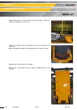
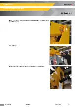
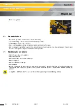
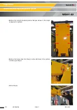
To install the new pads, go through the disassembly instructions in reverse order :
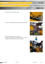
• Grease the surface of the new pads while making sure to put the adjustment palettes in the same places.
• Install the screws with threadlock.
• Install the back upper pads.
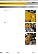
• Install the back upper lateral pads.
• Install the telescope cylinder : Grease the pin. Install the pin's stopper clevis. Check that the seals are on the
connections before reconnecting the hoses.
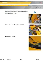
• Install the back lower pads.
• Install the back lower lateral pads.
• Install the output compensation cylinder : Grease the pin. Install the pin's stopper clevis.
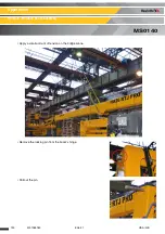
• Install the front lower pads.
• Install the front lateral pads.
• Install the front upper pads.
7 - Additional operations
• Clean the work area.
• Perform a static test by putting 290 kg / 639 lbs on the platform : Machine unfolded, 15 mn after checking the
performance of its parts (Arm cylinder, boom cylinder, telescope cylinder, compensation receiver cylinder, jib
cylinder).
In compliance with the country's laws, have the machine approved by an accredited organization.
Summary of Contents for HA26 RTJ PRO SW
Page 8: ...8 Maintenance Book ...
Page 120: ...120 4001055180 E 06 21 USA GB General data Pins and bearing inspection MS0002 Notes ...
Page 132: ...132 4001055180 E 06 21 USA GB General data Torque Values MS0005 Notes ...
Page 148: ...148 4001055180 E 06 21 USA GB Chassis Remove re install the hydraulic motor MS0119 Notes ...
Page 192: ...192 4001055180 E 06 21 USA GB Upper boom Remove Replace boom assembly MS0140 Notes ...
Page 200: ...200 4001055180 E 06 21 USA GB Upper boom Removing Replacing the pads MS0141 Notes ...
Page 230: ...230 4001055180 E 06 21 USA GB Lower arm Remove Replace arm cylinder MS0145 Notes ...
Page 244: ...244 4001055180 E 06 21 USA GB Electric Battery ies MS0149 Notes ...
Page 262: ...262 4001055180 E 06 21 USA GB Chassis Remove Re install wheel reduction gear MS0152 Notes ...
Page 268: ...268 4001055180 E 06 21 USA GB Chassis Wheel tightening procedure MP0001 Notes ...
Page 272: ...272 4001055180 E 06 21 USA GB Chassis Wheel reducer level procedure MP0002 Notes ...
Page 284: ...284 4001055180 E 06 21 USA GB Turntable Replacing the engine oil filter MP0004 Notes ...
Page 292: ...292 4001055180 E 06 21 USA GB Turntable Diesel filter replacement MP0005 Notes ...
Page 296: ...296 4001055180 E 06 21 USA GB Turntable Diesel filter replacement Kohler engine MP0005 Notes ...
Page 300: ...300 4001055180 E 06 21 USA GB Turntable Hydraulic oil filter replacement MP0006 Notes ...
Page 312: ...312 4001055180 E 06 21 USA GB Chassis Front axle locking function check MP0008 Notes ...
Page 316: ...316 4001055180 E 06 21 USA GB Turntable Air filter replacement MP0010 Notes ...
Page 330: ...330 4001055180 E 06 21 USA GB Platform Rotary cylinder tightness check MP0016 Notes ...
Page 334: ...334 4001055180 E 06 21 USA GB Platform Checking the platform MP0017 Notes ...
Page 342: ...342 4001055180 E 06 21 USA GB Turntable Slew ring clearance check MP0018 Notes ...
Page 346: ...346 4001055180 E 06 21 USA GB Turntable Torque tightening of the slew ring MP0019 Notes ...
Page 350: ...350 4001055180 E 06 21 USA GB Turntable Emptying the diesel tank MP0020 Notes ...
Page 362: ...362 4001055180 E 06 21 USA GB Turntable Starter battery inspection MP0023 Notes ...
Page 384: ...384 4001055180 E 06 21 USA GB Turntable Drain the engine oil MP0036 Notes ...
Page 388: ...388 4001055180 E 06 21 USA GB Turntable Drain the engine oil Kohler engine MP0036 Notes ...
Page 394: ...394 4001055180 E 06 21 USA GB Turntable Draining the wheel reducer MP0043 Notes ...

