311
4001055180
E 06.21
USA / GB
Chassis
Front axle locking function check
MP0008
Ensure the axles are extended and the boom is fully retracted,
lowered, and centered betweeen the rear wheels prior to
beginning lockout cylinder test :
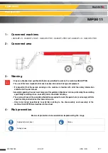
• Place a ramp 15 cm (6 in) high in front of the front right wheel.
• From platform control box, start engine.
• Place the drive control lever to the forward position and carefully drive
machine up ascension ramp until left front wheels is on top of block.
• Carefully extend the boom just enough to get it out of the transport
position.
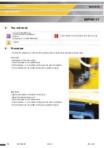
• With boom in this position, place drive control lever to reverse and
carefully drive machine off of block and ramp.
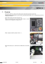
• Have an assistant check to see that left front or right rear wheel remains
elevated in position off of the ground.
• Carefully return the boom to the transport position. When boom reaches
the transport position, carefully activate drive to release cylinders. To
lockout cylinders should release and allow the wheel to rest on ground.
This operation must be realized with extremes precautions by standing
strongly on the platform by the contact with the ground.
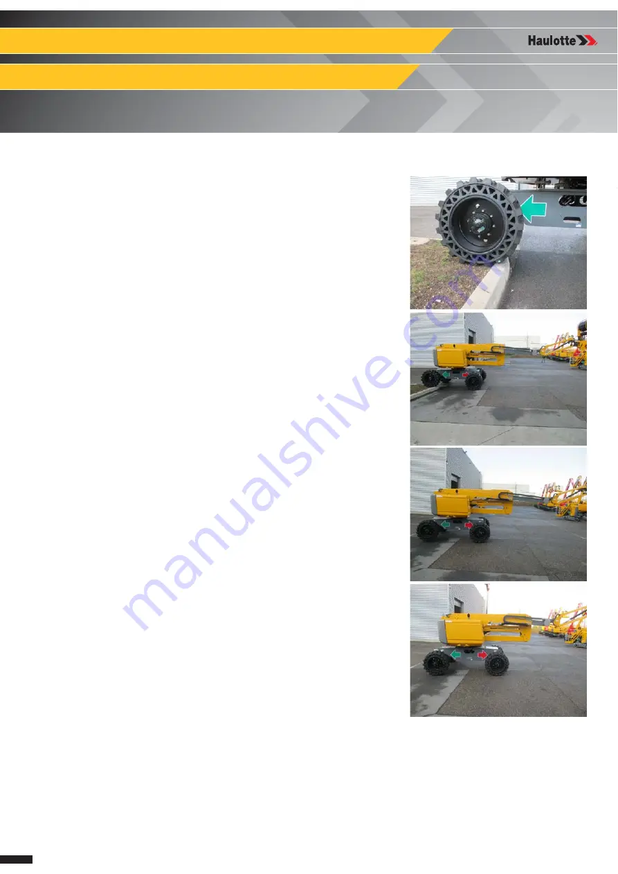
• Repeat the procedure for the right oscillation cylinder checking to see
that the right front or left rear wheel remains elevated in position off of
the ground.
• If lockout cylinders do not function properly, have qualified personnel
correct the malfunction prior to any further operation.
Summary of Contents for HA26 RTJ PRO SW
Page 8: ...8 Maintenance Book ...
Page 120: ...120 4001055180 E 06 21 USA GB General data Pins and bearing inspection MS0002 Notes ...
Page 132: ...132 4001055180 E 06 21 USA GB General data Torque Values MS0005 Notes ...
Page 148: ...148 4001055180 E 06 21 USA GB Chassis Remove re install the hydraulic motor MS0119 Notes ...
Page 192: ...192 4001055180 E 06 21 USA GB Upper boom Remove Replace boom assembly MS0140 Notes ...
Page 200: ...200 4001055180 E 06 21 USA GB Upper boom Removing Replacing the pads MS0141 Notes ...
Page 230: ...230 4001055180 E 06 21 USA GB Lower arm Remove Replace arm cylinder MS0145 Notes ...
Page 244: ...244 4001055180 E 06 21 USA GB Electric Battery ies MS0149 Notes ...
Page 262: ...262 4001055180 E 06 21 USA GB Chassis Remove Re install wheel reduction gear MS0152 Notes ...
Page 268: ...268 4001055180 E 06 21 USA GB Chassis Wheel tightening procedure MP0001 Notes ...
Page 272: ...272 4001055180 E 06 21 USA GB Chassis Wheel reducer level procedure MP0002 Notes ...
Page 284: ...284 4001055180 E 06 21 USA GB Turntable Replacing the engine oil filter MP0004 Notes ...
Page 292: ...292 4001055180 E 06 21 USA GB Turntable Diesel filter replacement MP0005 Notes ...
Page 296: ...296 4001055180 E 06 21 USA GB Turntable Diesel filter replacement Kohler engine MP0005 Notes ...
Page 300: ...300 4001055180 E 06 21 USA GB Turntable Hydraulic oil filter replacement MP0006 Notes ...
Page 312: ...312 4001055180 E 06 21 USA GB Chassis Front axle locking function check MP0008 Notes ...
Page 316: ...316 4001055180 E 06 21 USA GB Turntable Air filter replacement MP0010 Notes ...
Page 330: ...330 4001055180 E 06 21 USA GB Platform Rotary cylinder tightness check MP0016 Notes ...
Page 334: ...334 4001055180 E 06 21 USA GB Platform Checking the platform MP0017 Notes ...
Page 342: ...342 4001055180 E 06 21 USA GB Turntable Slew ring clearance check MP0018 Notes ...
Page 346: ...346 4001055180 E 06 21 USA GB Turntable Torque tightening of the slew ring MP0019 Notes ...
Page 350: ...350 4001055180 E 06 21 USA GB Turntable Emptying the diesel tank MP0020 Notes ...
Page 362: ...362 4001055180 E 06 21 USA GB Turntable Starter battery inspection MP0023 Notes ...
Page 384: ...384 4001055180 E 06 21 USA GB Turntable Drain the engine oil MP0036 Notes ...
Page 388: ...388 4001055180 E 06 21 USA GB Turntable Drain the engine oil Kohler engine MP0036 Notes ...
Page 394: ...394 4001055180 E 06 21 USA GB Turntable Draining the wheel reducer MP0043 Notes ...


