background image

rev. 122817MH


©2017 HAUSMANN INDUSTRIES, INC.


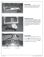
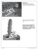
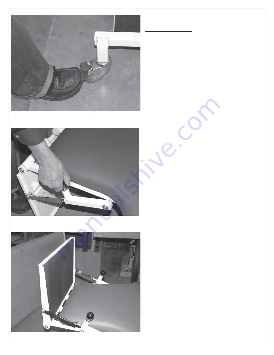
Fig. 4


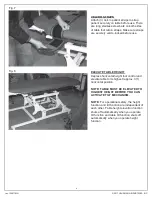
Fig. 5


Fig. 6


5


LOCKING CASTERS


You must lock brakes of all (4) casters by depress- 
ing brake pedal down before patient use.


PIVOTING FOOT PLATE


You must adjust angle position before patient use. 
There are two black spring loaded control handles. 
Lift up and turn knobs to “open”. Adjust foot plate 
into an approximate 90° right angle position (there 
are adjustment holes on steel rod). Turn both knobs 
to re-lock the foot plate into desired position as 
shown. Turn both knobs to snap lock the ft plate into 
desired pos as shown in fig 6 below.


NOTE: DO NOT OPERATE TILT IF FOOT PLATE 
IS IN “OUT OF WAY” POSITION AS SHOWN IN 
FIG 5.


Foot plate shown in 90° operational position.


Summary of Contents for 6058

Page 1: ...ay vinyl Equipped with 3 safety straps with hook and loop closures Electric Hi Lo lift mechanism adjusts from 19 low wheelchair height to 33 high Tilts from horizontal to 90 Unit should be raised to max height before tilting Tilt angle indicator on both sides of table Pivoting Footboard with rubber tread Angle of the Footboard tilt is adjustable with spring loaded controls on both sides Hands free...

Page 2: ...st quality materials are utilized in the construction of the table and the latest industry proven fabrication methods are used NOTE FOR OPERATIONAL SAFETY THE HEIGHT FUNCTION AND TILT FUNCTION ARE INDEPENDENT OF EACH OTHER TABLE HEIGHT ELEVATION FUNCTION SHUTS OFF AUTOMATICALLY WHEN YOU OPERATE TILT FUNCTION AND TABLE TILT FUNCTION SHUTS OFF AUTOMATICALLY WHEN YOU OPERATE HEIGHT FUNCTION FOR PROFE...

Page 3: ... dealer from which it was purchased or to the nearest authorized service agent together with a full report freight paid and insured Under No Circumstances Shall Hausmann Industries Inc or their agents or dealers be liable in any manner whatsoever for any compensation or damages to any person occasioned by this table for any loss injury or any damage occasioned by or as a result of misuse or abuse ...

Page 4: ... at bottom rear of frame Plug power cord into 3 pole wall receptacle preferably hospital grade that is correctly wired to building power system Periodically check grounding continuity and check for frayed wires or worn insulation on power cord FOOT CONTROL Unit has low voltage electrical foot switch Con trols for Up and Down of horizontal eleva tion are on left facing and controls for Up and Down ...

Page 5: ... black spring loaded control handles Lift up and turn knobs to open Adjust foot plate into an approximate 90 right angle position there are adjustment holes on steel rod Turn both knobs to re lock the foot plate into desired position as shown Turn both knobs to snap lock the ft plate into desired pos as shown in fig 6 below NOTE DO NOT OPERATE TILT IF FOOT PLATE IS IN OUT OF WAY POSITION AS SHOWN ...

Page 6: ... use ELEVATE TABLE HEIGHT Depress horizontal height foot control and elevate table to its highest approx 33 horizontal position NOTE TABLE MUST BE ELEVATED TO HIGHEST HEIGHT BEFORE YOU CAN ACTIVATE TILT MECHANISM NOTE For operational safety the height function and tilt function are independent of each other Table height elevation function shuts off automatically when you operate tilt function and ...

Page 7: ...ilt mechanism by depressing Up Tilt pedal of foot control Table is now at maximum 90 tilt or any angle tilt angle from 0 to 90 that you select NOTE WITH TABLE AT MAXIMUM 33 HEIGHT USE FOOT CONTROL TO LOWER THE TILT TOP DOWN TO FLAT HORIZONTAL TILT TOP MUST BE AT FLAT HORIZONTAL BEFORE YOU CAN LOWER TABLE HEIGHT 7 Fig 10 ...

Page 8: ... position You must use two hands as shown to lower or raise top NOTE WHENEVER YOU ACTIVATE EMERGENCY RELEASE HANDLE TO LOWER TOP YOU MUST MANUALLY USE RED HANDLE TO RAISE THE LOWERED TOP BACK TO THE TILT ANGLE IT WAS IN BEFORE YOU LOWERED IT FOR EXAMPLE IF THE TOP WAS AT 90 WHEN THE EMERGENCY OCCURRED YOU MUST MANUALLY USE RED RELEASE HANDLE TO RETURN THE TOP BACK TO ORIGINAL 90 TILT POSITION BEFO...

Page 9: ... Megamat MC4 6000N DETAIL OF HEIGHT ELEVATION MOTOR AND UNIT CONTROL BOX LOCATED AT BOTTOM REAR OR TABLE CHASSIS Motor Is Dewarts Model Megamat MC4 6000N Control Box Is Dewarts Model MCL 120 V 60 HZ 3 15 AMPS Intermittant Operation 2 min 18 min DETAIL OF CONTROL BOX AND PORT CONNECTIONS Power Cord Port 1 Foot Control Port 2 Height Motor Port 3 Tilt Motor 9 ...

Page 10: ...lt function Once you activate tilt you disable height function DETAIL OF UPPER TILT MICRO SWITCH ASSEMBLY OPEN When microswitch on the tilt is open it disables the horizontal height function and you are able to operate the vertical tilt DETAIL OF UPPER TILT MICRO SWITCH ASSEMBLY CLOSED When microswitch is closed you are able to operate the horizontal height function and it disables the vertical ti...

Reviews: