background image

24

ENGLISH

!

!

!

!

SET-UP

WARNING! 

After removing it from the carton, and before you can use your 

compressor, check for possible shipping damage to the unit and its components

WARNING! 

If you discover any damage, do not operate the compressor until it 

is repaired. Failure to do so could result in possible serious injury.

WARNING! 

Check for missing parts and components If any parts are missing, 

do not operate the compressor until they have been replaced. Failure to do so 

could result in possible serious injury.


z

Add oil preparatory to using your compressor


z

Retain packing materials until inspection is complete and the compressor runs 

satisfactorily

You will need:


z

8 fl.oz. SAE-20 or SAE-10 non-detergent compressor oil


z

Small flat screwdriver

AIR FILTER INSTALLATION

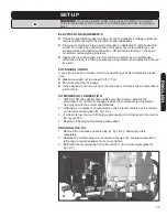
1.  Loosely thread the air inlet filter / muffler (K, fig.1 & 2) into the hole in the side 

of the cylinder head (fig.2).

2.  To tighten it, use a 24 mm open-end or combination wrench on the hexagonal 

surfaces of the threaded end of the filter, rather than using your hand on the 

light metal housing, which can deform or break off easily.

OIL

WARNING! 

This compressor requires oil of the correct type and quantity to 

run. Do not start it without first following all the steps in this section.

1.  Be sure the compressor is on a level surface.
2.  With the screwdriver, pry off and remove the shipping plug from the top of the 

crankcase (Q, fig.3) revealing the oil fill hole.

3.  Through this hole, fill the oil reservoir with SAE-20 (API CG/CD heavy duty), 

non-detergent compressor oil. In extreme winter conditions, use lighter SAE-10 

weight.

4.  There may be some oil left over from the manufacturing process already in the 

reservoir.

5.   Check the oil level sight glass (N, fig.1 & 3). The oil should show level with the 

red dot in the centre of the viewing window. Be careful not to overfill.

6.  Find the oil fill plug (L in fig.1 & 4). It is usually shipped separately from the 

compressor and enclosed with this manual. Be sure there is a rubber O-ring on 

the upper part of the threaded end.

7.  Put a little pipe thread sealing tape on the threaded end of the oil fill plug.
8.  Gently screw the oil breather cap into the oil fill hole. Do not cross-thread or 

overtighten.

NoTE: 

Before installing and using this unit, inspect carefully for damage and 

corrosion. Make sure the tank, compressor, motor and pump are undamaged 

and that all screws and caps are securely tightened.

INSTALLATION AND LOCATION

Locate the compressor in a clean, dry and well-ventilated area; on a firm, level 

surface. It should be located 12 to 18 inches (30 to 45 cm) from a wall or any other 

obstruction that would interfere with the air flow. It is equiped with heat dissipation 

fins that allow for proper cooling. Keep them and other parts free of dust or dirt that 

could interfere with cooling. A clean compressor runs cooler and provides longer 

service. Do not place anything on top of the compressor.

Summary of Contents for 57265002

Page 1: ...maged or missing part most replacement parts ship from our facility in two business days For immediate help with assembly or for additional product information call our toll free number 1 866 206 0888 C Notre personnel du Service à la clientèle est disponible pour vous aider Dans le cas d une pièce endommagée ou manquante la plupart des pièces de remplacement seront expédiées de notre usine en deu...

Page 2: ...risque d incendie de choc électrique et de blessures corporelles LIRE TOUTES LES INSTRUCTIONS AVANT D UTILISER CET Équipement Avertissement Prenez le temps de lire et de comprendre toutes les instructions Ne pas suivre toutes les instructions décrites ci dessous peut entraîner des blessures corporelles sérieuses Aire de travail 1 Conservez l aire de travail propre Le désordere invite les blessures...

Page 3: ...ueur de 25 pi 7 62 m Longueur de 50 pi 15 24 m Longueur de 75 pi 22 86 m Longueur de 100 pi 30 48 m Longueur de 150 pi 45 72 m Longueur de 200 pi 60 96 m 0 5 A cal 16 cal 16 cal 16 cal 14 cal 12 cal 12 5 1 8 A cal 16 cal 16 cal 14 cal 12 cal 10 Ne pas utiliser 8 1 12 A cal 14 cal 14 cal 12 cal 10 Ne pas utiliser Ne pas utiliser 12 1 15 A cal 12 cal 12 cal 10 cal 10 Ne pas utiliser Ne pas utiliser ...

Page 4: ...e de la portée des enfants 7 Ne pas forcer l équipement Il fera un meilleur travail de manière plus sécuritaire au rythme pour lequel il est conçu 8 Utilisez l équipement approprié Ne pas forcer un petit équipement ou un accessoire à faire le travail d un équipement industriel plus gros Ne pas utiliser un équipement à une fin pour laquelle il n a pas été conçu 9 Examinez pour des pièces endommagée...

Page 5: ...stement requis Ne modifiez jamais le réglage Ceci annulera automatiquement votre garantie 3 Manostat Le manostat est préréglé à l usine pour une performance optimale Ne contournez pas et n enlevez pas ce manostat Une pression trop élevée peut causer des dommages graves à l équipement ou des blessures corporelles graves 4 Moteur et pompe de compresseur Les compresseurs d air deviennent chauds lors ...

Page 6: ...8 kPa 0 150 m3 620 5 kPa le plus haut fourni par un circuit de ménage de 15 ampères et 120 volts z z Pression maximale 150 lbs po2 1034 2 kPa z z Cycle de travail 50 z z Poids 154 3 lbs 70 kg z z Poids de l ensemble 161 lbs 73 kg Description fonctionelle Votre nouveau compresseur peut être utilisé avec des vaporisateurs de peinture d herbicide et d insecticide des équipements pneumatiques un pisto...

Page 7: ...suelle du niveau d huiles O Bouchon de vidange du carter P Robinet de purge ASSEMBLAGE Avertissement Après l avoir retiré du carton d emballage et avant de pouvoir utiliser votre compresseur vérifier les dommages éventuels d expédition de l appareil et de ses éléments Avertissement En cas de dommage ne pas faire fonctionner le compresseur avant sa réparation Omettre de la faire pourrait entraîner ...

Page 8: ...eur visuel de niveau N dans fig 1 et 3 L huile devrait indiquer un niveau avec le point rouge au centre de l indicateur visuel de niveau 6 Repérez le bouchon reniflard L dans la fig 1 et 4 Il est habituellement livré séparément du compresseur et inclus avec ce manuel Assurez vous qu il y a un joint torique de caoutchouc sur l embout fileté 7 Appliquez un peu de ruban scellant sur l embout fileté d...

Page 9: ...épasser 50 pi 15 m z z Grosseur maximum du fil cal 14 z z Si le cordon de rallonge est trop long ou le fil est trop petit le compresseur ne pourra démarrer HUILE 1 VÉRIFIEZ la qualité et la quantité d huile chaque fois avant de faire fonctionner le compresseur Ne pas ajouter de l huile lorsque lecompresseur fonctionne Utilisez l huile contenant les propriétés requises 2 Lorsque le compresseur est ...

Page 10: ...e centre de service Remarque Si le manostat n arrête pas le compresseur pour une quelconque raison celui ci dispose d une soupape de sécurité représentée en E fg 1 5 qui s ouvrira automatiquement lorsque la pression dans le réservoir deviendra trop forte INSTRUCTIONs D UTILISATION 1 Assurez vous que l interrupteur marche arrêt J fig 1 est vers le bas en position d ARRÊT 2 Fermez tournez le bouton ...

Page 11: ...e en tournant son capuchon de métal pour l ouvrir Retirer l élément du filtre et le nettoyer soigneusement avec de l eau et du savon ENTRETIEN MENSUELE z z Pour vérifier s il y a des fuites au système d air appliquez de l eau savonneuse sur tous les joints S il y a une fuite serrez les joints z z Vérifiez à ce que les écrous et les boulons sont toujours bien serrés APRÈS 250 HEURES OU SIX 6 MOIS l...

Page 12: ...oidissement approprié z z Inspectez le cordon d alimentation régulièrement et faites le remplacer par un centre de réparation autorisé s il est endommagé z z Vérifiez régulièrement si les réservoirs ont des bosses des fissures ou autres dommages Ne pas utiliser si une pièce du système pressurisé est endommagée z z Un centre de réparation autorisé doit effectuer toutes les réparations les modificat...

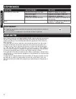
Page 13: ...iser Peinture vaporisée sur les pièces internes du moteur Consulter le centre de service Le disjoncteur déclenche ou un fusible saute trop souvent Basse tension Consulter un électricien Longueur excessive de fil Essayer de faire fonctionner le compresseur sans rallonge Passages d air restreints Consulter le centre de service Contre pression dans la hauteur d élévation Remplacer la soupape de reten...

Page 14: ...tre tout défaut de fabrication pendant 36 mois suivant la date de l achat Cette garantie n a aucune incidence sur vos droits prévus par la loi En cas de mauvais fonctionnement de votre équipement bris pièces manquantes etc composez notre numéro sans frais pour parler à un technicien de maintenance au 1 866 206 0888 du lundi au vendredi de 8 h à 18 h heure de l Est RONA se réserve le droit de répar...

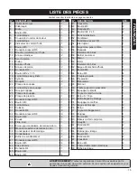
Page 15: ... Filtre à air 1 36 Écrou pour mécanisme de remise à zéro 1 37 Mécanisme externe de remise à zéro 1 38 Condensateur de démarrage 1 39 Condensateur 1 40 Boîtier de condensateur 2 41 Rondelle à ressort Φ5 8 42 Boulon M5 4 43 Prise de terre 1 44 Rondelle Φ4 1 45 Boulon M4 1 46 Boulon M5 4 NO DESCRIPTION QTÉ 47 Couvercle 1 48 Boulon M5 2 49 Rondelle Φ5 2 50 Boulon St4 2 x 8 2 51 Anneau élastique 1 52 V...

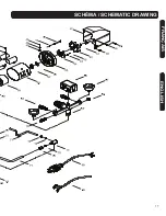
Page 16: ...16 FRANÇAIS ENGLISH SCHÉMA SCHEMATIC DRAWING ...

Page 17: ...17 FRANÇAIS ENGLISH SCHÉMA SCHEMATIC DRAWING ...

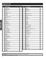
Page 18: ... Φ8 8 33 Bolt M8 4 34 Elbow 1 35 Air filter 1 36 Outside reset nut 1 37 Outside reset 1 38 Start capacitor 1 39 Capacitor 1 40 Capacitor box 2 41 Spring washer Φ5 8 42 Bolt M5 4 43 Grounding plate 1 44 Washer Φ4 1 45 Bolt M4 1 46 Bolt M5 4 NO DESCRIPTION QTY 47 Cover 1 48 Bolt M5 2 49 Washer Φ5 2 50 Bolt St4 2 x 8 2 51 Circlip 1 52 Fan 1 53 Spring washer Φ4 1 54 Switch 1 55 Rear bearing crank 1 56...

Page 19: ...IONS before using this equipment warning Take the time to read and understand these instructions Failure to follow all instructions listed below may result in serious personal injury work area 1 Keep work area clean Cluttered areas invite injuries 2 Consider the work area environment Consider work area environment Don t use power tools or equipment in damp wet or poorly lit locations Don t expose ...

Page 20: ... Wear protective hair covering to contain long hair and keep it from harm 2 Use eye protection Use a full face mask if the work you re doing produces metal filings dust or wood chips ANSI Z87 1 compliant approved safety glasses with rigid side shields or goggles are acceptable in other situations Wear a clean dust mask if the work involves creating a lot of fine or coarse dust 3 Don t overreach Ke...

Page 21: ...h does not turn it on and off properly 10 Never use this equipment if it is leaking air has missing or damaged parts guards or shields or requires repair Make sure all screws and caps are securely tightened 11 Do not use the air hose to move the compressor Release the pressure in the storage tank before moving 12 Maintain equipments with care Keep equipment clean for better and safer performance F...

Page 22: ...ame specification as the original equipment Warning The warnings cautions and instructions detailed in this manual cannot cover all possible conditions and situations that occur It must be understood by the operator that COMMON SENSE AND CAUTION ARE FACTORS that cannot be built into this product but MUST BE SUPPLIED BY THE OPERATOR SpEcifications z z Motor 120 volts 60 Hz 15 amps z z 3 peak HP z z...

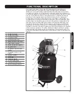
Page 23: ... is compressed The inlet valve closes and compressed air is forced out through the discharge valve through the check valve and into the air receiver A check valve prevents it from going back into the pump Working air is not immediately available Air becomes available for use when the receiver pressure is above that required by the regulator at the air service connection The pump continues to add a...

Page 24: ...pping plug from the top of the crankcase Q fig 3 revealing the oil fill hole 3 Through this hole fill the oil reservoir with SAE 20 API CG CD heavy duty non detergent compressor oil In extreme winter conditions use lighter SAE 10 weight 4 There may be some oil left over from the manufacturing process already in the reservoir 5 Check the oil level sight glass N fig 1 3 The oil should show level wit...

Page 25: ...sion cord when operating your air compressor please note z z Maximum length not to exceed 50 ft 15 m z z Minimum wire size 14 gauge z z If the extension cord is too long or the wire size is too small the air compressor will not start COMPRESSOR LUBRICATION 1 CHECK THE OIL quantity and quality every time before operating the compressor Do not add or change oil while the compressor is in operation U...

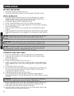
Page 26: ...as a safety valve pictured at E fig 1 5 which will open automaically when pressure in that tank becomes too great OPERATIng instructions 1 Be sure the On Off switch J fig 1 is swung down in the Off position 2 Close turn the knurled knob out clockwise the air tank moisture release petcock P fig 1 6 3 Plug in the power cord 4 Pull up on the On Off switch to turn the unit on 5 Adjust the regulator H ...

Page 27: ...d clean it thoroughly with soap and water MONTHLY MAINTENANCE z z Inspect air system for leaks by applying soapy water to all joints Tighten those joints if leakage is observed z z Check that all nuts and bolts stay tight 250 HOURS or 6 MONTHS whichever comes first OIL CHANGE z z After 250 hours of use your compressor will require an oil change z z Paint spraying operations or dusty environments m...

Page 28: ...ooling vanes clear of dust and debris This will help pre vent possible electrical shorts and ensure proper cooling z z Inspect the cord regularly and have it replaced by an authorized repair facility if it is damaged z z Check the tanks regularly for dents cracks rust and other damage Do not use if any part of the pressurized system is damaged z z An authorized repair center should do any repairs ...

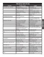
Page 29: ...e on pressure switch has not unloaded head pressure Move switch to Off and then restart Paint spray on internal motor parts Consult service centre Circuit breaker trips or fuse blows too often Low voltage Consult electrician Excessive wire length Try to run compressor without extension cord Restricted air passages Contact service centre back pressure in pump head Replace check valve Replace pressu...

Page 30: ...vice line at 1 866 206 0888 from 8 AM to 6 PM Monday to Friday Eastern time RONA reserves the right to repair or replace the defective equipment at its discretion Normal wear and tear including accessory wear is not covered under guarantee The product is guaranteed for 36 months if used for normal trade purposes Any guarantee is invalid if the product has been overloaded or subject to neglect impr...

Page 31: ...31 ENGLISH Notes ...

Reviews: