

PNT152
ENGLISH
14
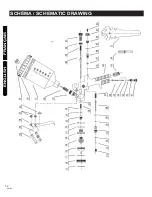
SCHEMATIC DRAWING
TABLE OF CONTENTS
p.12
p.13
p.15
p.17
p.17
p.18
p.20
p.21
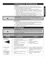
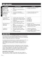
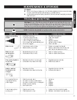
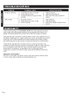
TROUBLESHOOTING
p.18
GENERAL SAFETY INSTRUCTIONS
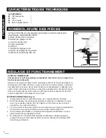
FUNCTIONAL DESCRIPTION
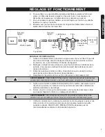
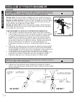
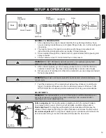
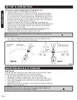
SETUP & OPERATION
MAINTENANCE & STORAGE
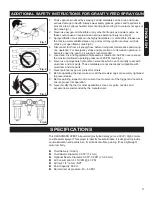
ADDITIONAL SAFETY INSTRUCTIONS FOR AIR-POWERED SPRAY GUN
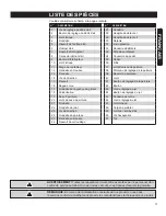
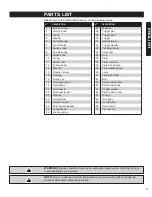
PARTS LIST
SPECIFICATIONS
p.14
SYMBOLS
p.22
WARRANTY
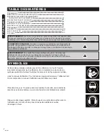
SYMBOLS
Some of the following symbols may be used on this tool. Please study them and
learn their meaning. Proper interpretation of these symbols will allow you to
operate the tool better and safer.
Read operator's manual: To reduce the risk of injury, user must read and
understand operator's manual before using this product.
Eye protection: Always wear safety goggles, safety glasses with side shields, or a
full face shield when operating this product.
Risk to hearing: Always wear ear protection when using this tool. Failure to do so
may result in hearing loss.
!
!
!
WARNING!
The warnings and precautions discussed in the manual cannot cover all
possible conditions and situations that may occur. It must be understood by the user
that common sense and caution are factors which cannot be built into this product,
but must be supplied by the user.
WARNING!
To avoid serious personal injury, do not attempt to use this product until
you read the manual thoroughly and understand it completely. Save this manual
and review frequently for continuing safe operation and instructing others who may
use this tool.
SAVE THIS MANUAL:
Keep this manual for the safety warning, precautions,
operations, inspections and maintenances. Keep the manual and the receipt in a
safe and dry place for future reference.


