!
PNT180
ENGLISH
20
Note:
Residual air pressure should not be present after the air supply is
disconnected. However, it is a good safety measure to attempt to discharge the tool
in a safe fashion after disconnecting to ensure that the tool is unpowered.
WORK PIECE AND WORK AREA SET UP
Warning!
Turn the tool off, detach the air supply, safely discharge any residual air
pressure in the tool, and release the throttle and/or turn the switch to its off position
before assembling or making any adjustments to the tool
1. Designate a work area that is clean and well-lit. The work area must not allow
access by children or pets to prevent distraction and injury.
2. Route the air hose along a safe path to reach the work area without creating a
tripping hazard or exposing the power cord to possible damage. The power cord
must reach the work area with enough extra length to allow free movement while
working.
3. There must not be hazardous objects, such as utility lines or foreign objects,
nearby that will present a hazard while working.
4. You must use personal safety equipment including, but not limited to, ANSI
approved eye and hearing protection, as well as heavy work gloves.
5. Before beginning work, protect area from sparks and debris that will fly off the
work surface.
6. Remove the plug from the air lnlet and thread the coupler plug onto the tool
using three to four wraps of thread sealing tape (sold separately).
7. If an automatic oiler is not used, add a few drops of pneumatic tool oil to the
airline connection before use. Add a few drops more after each hour of continual
use.
!
!
!
7. For optimal performance, install a quick connector to the tool and a quick coupler
on the hose, if applicable.
8. Verify that all of the connections in the air supply system are sealed in order to
prevent air from leaking.
WARNING!
TO PREVENT SERIOUS INJURY FROM ACCIDENTAL OPERATION
Do not install a female quick coupler on the tool. Such a coupler contains an air
valve that will allow the air tool to retain.
AIR PRESSURE SETUP BEFORE TOOL USE
Note:
Air flow, and therefore tool performance, can be hindered by undersized air
supply components.
1. The air hose must be long enough to reach the work area with enough extra
length to allow free movement while working.
2. Turn the tool’s throttle or switch to the off position; refer to Operation section for
description of controls.
3. Close the in-line safety valve between the compressor and the tool.
4. Turn on the air compressor according to the manufacturer’s directions and allow
it to build up pressure until it cycles off.The required air pressure has been
reached.
5. Adjust the air compressor’s output regulator so that the air output is enough to
properly power the tool, without exceeding the tool’s maximum air pressure at
any time. Adjust the pressure gradually while checking the air output gauge to
set the right pressure range.
6. Inspect the air connections for leaks. Repair any leaks found.
7. If the tool will not be used at this time, turn off and disconnect from air supply,
safely discharge any residual air pressure, and release the throttle and/or turn
the switch to its off position to prevent accidental operation.
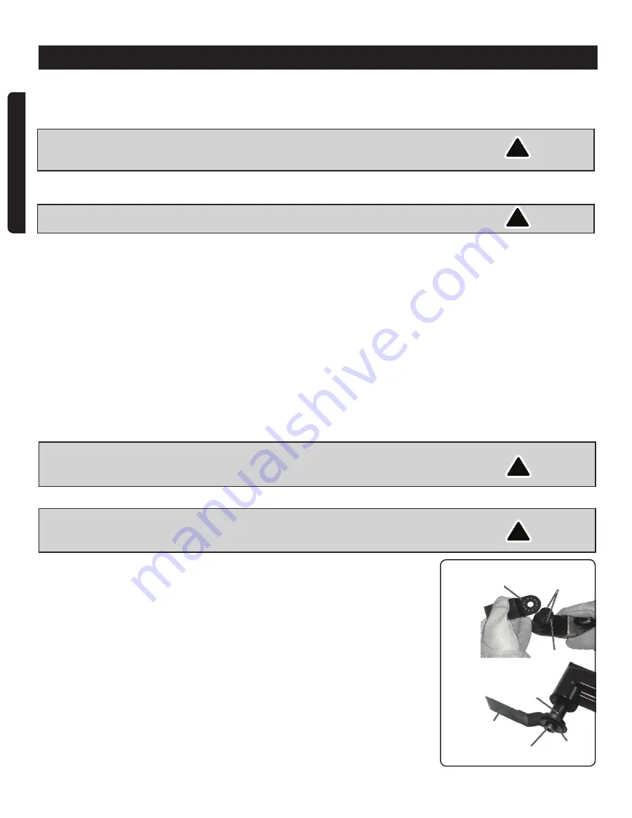
SETUP & OPERATION
Fig.3
Accessory-Angled
cutting blade
Output shaft (3)
Output shaft (3)
Cap screw(1)
Retainer (2)
Accessory-A
ngled cutting
blade
Pins


