background image

ENGLISH

22

CK104-CS

ASSEMBLY

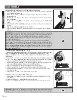
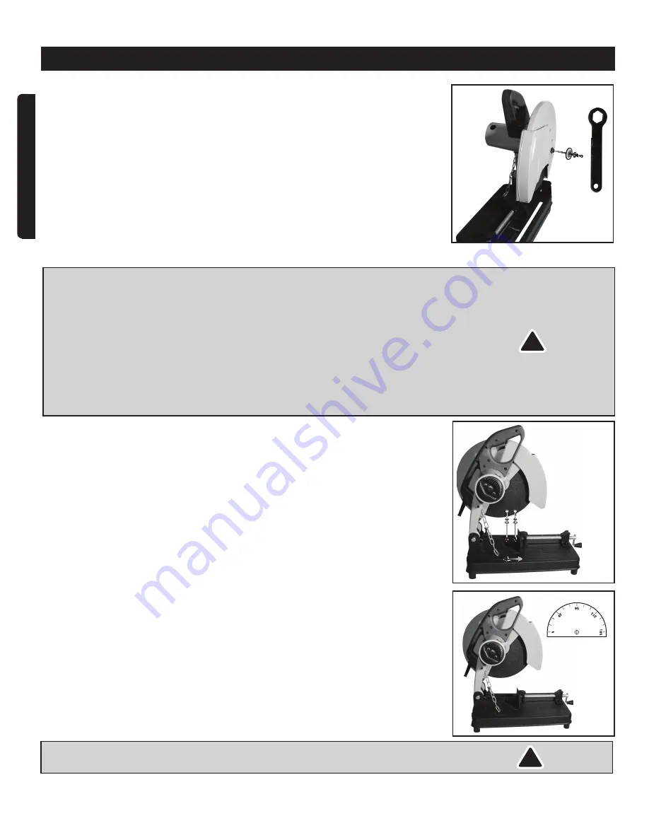
INSTALLING THE ABRASIVE CUTTING WHEEL (See Fig.5)

1.  Place the screw, washer, outer flange and arbor adapter (if used) through the hole 

in the new abrasive wheel.

2.  Place the inner flange onto the screw protruding to the back side of the new 

abrasive wheel.

3.  Holding the new abrasive wheel in one hand, align the screw into the threaded 

hole in the arbor.

4.  Push in the arbor shaft lock lever and turn the new abrasive wheel until the shaft 

locks.

5.  Hold the arbor shaft lock in place and use a wrench, turn the screw clockwise to 

tighten.

6.  Tighten the screw securely into the motor arbor.
7.  Replace the movable blade guard exposing the covering screw for the abrasive 

wheel.

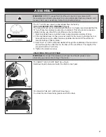
WARNING! 

Do not over-tighten the screw. Over tightening the screw can cause the 

abrasive wheel to crack resulting in premature failure. This could cause the abrasive 
wheel to break and fly off the arbor shaft when the trigger is engaged. Failure to 
adhere to this Warning could cause damage to the cut-off saw and severe injury or 
even death to the operator.
Use only a 14" diameter abrasive cut-off wheel rated to a minimum 4000 RPM. 
Cut-off wheels that do not match the mounting hardware, exceed a maximum 4400 
RPM or fall below the minimum 4000 RPM may sustain premature wear or breakage 
and fly off the cut-off saw or run eccentrically resulting in a loss of control. Failure to 
adhere to this Warning could cause damage to the cut-off saw and severe injury or 
even death to the operator.

ADJUSTING THE WORK VISE (See Fig.6)

The work vise is located on the base of the cut-off saw. The vise is made up of two 
parts: (1) a stationary fence which can be loosened and rotated from 0° to 45° 
degrees and (2) a movable clamp with an adjustable screw handle and a quick 
release lock.
The work vise will also move toward the rear of the base to allow larger workpieces to 
be cut. To set up and adjust the work vise, follow the directions below. See Figure 6.
1. Using a wrench, turn the two blots counterclockwise to loosen.
2. Rotate the work vise fence to the desired the angle by aligning the gauge on the 

vise base with the indicator groove in the Cut-off saw base.

3. Using a wrench, turn the two bolts clockwise to securely tighten.
4. Using a wrench, turn the two bolts counterclockwise and remove them.
5. Slide the stationary portion of the work vise over the last threaded hole in the 

Cut-off saw base.

6. Install one of the bolts into the hole to set vise in place.

DO NOT TIGHTEN AT THIS TIME. (See Fig.7)
7. Align the second hole of the work vise base with another threaded hole in the 

Cut-off base.

8. Install the second hex sockethead screw into the hole.
9. Using a wrench, turn the two hex socket-head cap screws clockwise to loosen.

CAUTION! 

The angled cut settings on the fence base are only approximate settings. 

Always check the accuracy of angled cut settings using a protractor or bevel gauge.

!

!

Fig.7

Fig.6

Fig.5

Summary of Contents for CK104-CS

Page 1: ...re produit Nous vous invitons à enregistrer votre produit en ligne afin de faciliter les communications pour ce faire veuillez visiter le www outilshaussmann com Register your product We invite you to register your product online to make future communications easier To do so simply visit our website www haussmanntools com Notre personnel du service à la clientèle est disponible pour vous aider Pou...

Page 2: ...NANT L ISOLATION DOUBLE Cet outil est doté d une isolation double Il est équipé d une fiche polarisée Une lamelle de la fiche est plus large que l autre et elle ne s insèrera dans une prise de courant polarisée que d une seule façon Si vous éprouvez des difficultés pour insérer la fiche inversez la Si elle ne s insère toujours pas ne tentez pas de modifier la fiche Demandez à un électricien qualif...

Page 3: ...rité Respectez les directives de lubrification et de changement des accessoires Gardez les poignées propres et sèches sans huile ni graisse 18 ÉVITEZ LA MISE EN MARCHE ACCIDENTELLE Assurez vous que l interrupteur est à la position ARRÊT avant de brancher l outil 19 N UTILISEZ PAS L OUTIL SI L INTERRUPTEUR MARCHE ARRÊT NE FONCTIONNE PAS CORRECTEMENT Faites réparer votre outil avant de l utiliser 20...

Page 4: ...touchent la pièce Si le disque abrasif est excentré ou si la bordure semble détériorée le remplacer immédiatement Si les vibrations persistent vérifier les roulements et l arbre du moteur et les réparer ou les remplacer dès que possible Des VIBRATIONS EXCESSIVES peuvent endommager sérieusement la pièce ainsi que la scie à découper RÉGLER LA TABLE DE COUPE AVANT CHAQUE UTILISATION La table doit êtr...

Page 5: ...ents de toutes parts Ne modifier en aucune façon ou sous aucune forme les carters supérieurs et inférieurs protégeant le disque abrasif NE PAS FAIRE FONCTIONNER LA SCIE SI LES CARTERS NE SONT PAS EN POSITION NE JAMAIS EFFECTUER DE DÉCOUPES EN PRÉSENCE DE GAZ OU LIQUIDES INFLAMMABLES TOUJOURS ÉLOIGNER LES BRAS MAINS ET DOIGTS de la pièce à travailler lorsqu elle est sur la table et que la scie est ...

Page 6: ...e mais si cela s avère nécessaire suivre les instructions ci dessous La scie à découper de 14 po est vendue pré assemblée OUTILS NÉCESSAIRES AU MONTAGE Fig 2 Les outils illustrés ne sont pas compris avec la scie Il est fortement recommandé de monter solidement la scie à découper sur un support d outil approprié On évitera ainsi toute vibration excessive en l utilisant Monter la scie sur un support...

Page 7: ... levier de blocage de la tige de l arbre en position et à l aide d une clé hexagonale serrer la vis dans le sens horaire 6 Bloquer fermement la vis sur l arbre du moteur 7 Remettre le protège disque amovible afin d accéder à la vis du disque abrasif AVERTISSEMENT Ne pas bloquer à fond la vis Si la vis est trop serrée le disque abrasif risque de se fendre et d être prématurément fragilisé Le disque...

Page 8: ...raire pour les desserrer ATTENTION Les réglages des angles de coupe obtenus sur le socle du guide sont approximatifs Toujours vérifier la précision des réglages des coupes en biseau à l aide d un rapporteur ou d un guide de biseau UTILISATION DU LEVIER DE DÉVERROUILLAGE RAPIDE Voir Fig 8 L étau de blocage est équipé d une mâchoire sur vis filetée et d une poignée de serrage La mâchoire est aussi é...

Page 9: ...e sens horaire pour caler fermement la pièce à couper dans l étau 3 Brancher le cordon d alimentation dans une prise C A AVEC MISE À LA TERRE 4 Saisir la poignée et placer le pouce sur le bouton de sécurité 5 Appuyer sur le bouton de sécurité avec le pouce Presser sur la gâchette Relâcher le bouton de sécurité 6 Attendre que la lame de scie tourne à pleine vitesse 7 Abaisser lentement la poignée t...

Page 10: ...4 Câblage électrique endommagé 5 Disque fendu ébréché ou voilé NETTOYAGE Tous les jours À l aide d une brosse à poils doux d un chiffon ou d un aspirateur d atelier retirer toutes les chutes poussières ou autres débris autour de la scie Après le nettoyage lubrifier toutes les pièces mobiles avec de l huile de graissage adaptée AVERTISSEMENT NE PAS UTILISER D HUILE DE GRAISSAGE SUR LE DISQUE ABRASI...

Page 11: ...l interrupteur à OFF arrêt retirer la clé de sûreté et débrancher l outil de la source d alimentation c a Si le moteur refuse de tourner quelle qu en soit la raison appeler le service à la clientèle au numéro indiqué en page couverture SOLUTION La scie refuse de démarrer 1 Outil débranché 2 Disjoncteur déclenché ou fusible grillé 3 Cordon d alimentation endommagé 4 Balais au carbone usagés ou endo...

Page 12: ...ue non aligné avec le guide 3 Utilisation d une force excessive pour réaliser la coupe 4 Déplacement de la pièce 1 Vérifier et ajuster le guide 2 Vérifier et ajuster le disque 3 Réduire la pression sur les coupes laisser le disque réaliser la coupe 4 Serrer solidement la pièce dans l étau Bras de la scie refusant de bouger 1 Pincement du carter du disque auto rétractable 1 Vérifier qu aucune pièce...

Page 13: ... l outil défectueux à sa discrétion L usure normale y compris l usure des accessoires n est pas couverte par cette garantie Ce produit est garanti durant 36 mois s il est utilisé de façon normale Toute garantie est invalide si le produit a été utilisé en surcharge ou de façon non recommandée ou a fait l objet de négligence ou de réparations non effectuées par un agent autorisé L usage professionne...

Page 14: ... M5X14 Vis M4X10 Rondelle à ressort Rondelle Culbuteur Bloc de butée Rondelle à ressort Vis M6X12 Stator Palier d essieu Rotor Déflecteur d air Palier d essieu Broche Ressort Couvercle du milieu Protecteur de meule Vis M5X60 Protecteur Vis M4X8 Protecteur Plaque de friction Boulon M6X12 Palier d essieu Circlip Engrenage Couvercle avant Palier d essieu Clavette NO DESCRIPTION 77 78 79 80 81 82 83 8...

Page 15: ...15 FRANÇAIS ENGLISH SCHÉMA SCHEMATIC DRAWING ...

Page 16: ...r Screw M5X14 Screw M4X10 Spring Washer Washer Rocker Arm Stop Block Spring Washer Screw M6X12 Stator Axle Bearing Rotor Air Deflector Axle Bearing Self Lock Pin Spring Middle Cover Grinding Wheel Guard Screw M5X60 Guard Screw M4X8 Guard Friction Plate Bolt M6X12 Axle Bearing Circlip Gear Front Cover Axle Bearing Woodruff Key NO DESCRIPTION 77 78 79 80 81 82 83 84 85 86 87 88 89 90 91 92 93 94 95 ...

Page 17: ...arized outlet only one way If you have difficulty inserting the plug try reversing it If it still doesn t fit do not alter the plug have a qualified electrician install a polarized outlet 5 PREVENT ELECTRIC SHOCKS Prevent body contact with grounded surfaces pipes radiators ranges and refrigerator enclosures When your body is grounded the risk of electric shock increases When working wherever live ...

Page 18: ... Keep handles dry clean and free from oil and grease 18 AVOID UNINTENTIONAL STARTING Be sure the switch is in the OFF position before plugging in 19 DO NOT USE THE TOOL IF IT CANNOT BE SWITCHED ON OR OFF Have your tool repaired before using it 20 DISCONNNECT THE PLUG FROM POWER BEFORE MAKING ANY ADJUSTMENTS Changing attachments or accessories can be dangerous if the tool could accidentally start 2...

Page 19: ...VE VIBRATION can cause severe damage to both the workpiece and the cut off saw ADJUST THE TOOL TABLE BEFORE EACH USE The tool table should be tightened and placed at the proper angle for the cutting job before the Cut off saw is put into use DO NOT STAND DIRECTLY IN FRONT OF THE CUT OFF SAW when it is first turned on Loose fragments could fly off at high speeds possibly causing injury NEVER REACH ...

Page 20: ...y hand The abrasive wheel can seize in the workpiece causing it to spin rapidly This will cause loss of control of the workpiece resulting in severe injuries or damage to the workpiece and Cut off saw NEVER APPLY A COOLANT DIRECTLY TO THE WORKPIECE WHILE IT IS IN CONTACT WITH THE ABRASIVE WHEEL Coolant can weaken the makeup of the abrasive wheels causing them to fail REDUCE THE RISK OF UNINTENTION...

Page 21: ...ate a variety of tools 2 If the tool stand does not have an exact match for the holes try to align the tool base with as many pre drilled holes as possible Mark and drill new holes for mounts that have missing holes 3 Insert four 1 4 X 20 screws and washers through the underside of the tool stand and up through the rubber feet on the base of the cut off saw The length of the screws should be 1 25 ...

Page 22: ...n a loss of control Failure to adhere to this Warning could cause damage to the cut off saw and severe injury or even death to the operator ADJUSTING THE WORK VISE See Fig 6 The work vise is located on the base of the cut off saw The vise is made up of two parts 1 a stationary fence which can be loosened and rotated from 0 to 45 degrees and 2 a movable clamp with an adjustable screw handle and a q...

Page 23: ...the bolt to secure the spark shield in position If any abnormal sounds are heard or abnormal smells or smoke is visible when Cut off saw is started DISCONTINUE USE IMMEDIATELY TURN OFF SAW AND REMOVE IT FROM THE AC POWER SOURCE These could be warning signs of imminent DANGER DO NOT USE CUT OFF SAW IF ANY DAMAGE IS SUSPECTED Failure to adhere to this WARNING could result in damage to the tool or se...

Page 24: ...wheel fail to pass through the workpiece raise the handle until it clears Turn off the cut off saw and remove the power cord from the AC receptacle Refer to SETTING THE cut OFF WHEEL DEPTH GAUGE 9 Once the cut is completed turn off the cut off saw by releasing the trigger switch This also allows the safety button to return to the OFF position 10 Unplug the cut off saw from the AC power source Ensu...

Page 25: ...ly maintenance free Closed type grease sealed ball bearings are used throughout the cut off saw These bearings are packed with grease at the factory and should last the life of the cut off saw The only required maintenance is covered in the CLEANING section above If this particular model cut off saw is equipped with replaceable carbon brushes on the motor there may become a time they need replacin...

Page 26: ... or too long 2 Low voltage from AC power source 1 Replace cord 2 Consult certified electrical contractor Cut off saw vibrates exces sively during cut 1 Saw not mounted securely to workbench 2 Damaged cut off wheel 3 Workpiece incorrectly clamped in vise 1 Tighten all mounting hard ware See Figure 1 2 Replace cut off wheel 3 Clamp workpiece securely in vise Cut off saw does not make accurate cuts 1...

Page 27: ...es not affect your statutory rights In case of any malfunction of your tool failure missing part etc please contact one of our service technicians at our toll free service line at 1 866 206 0888 from 8 AM to 6 PM Monday to Friday Eastern time RONA reserves the right to repair or replace the defective tool at its discretion Normal wear and tear including accessory wear is not covered under guarante...

Reviews: